This thread has been locked.

If you have a related question, please click the "Ask a related question" button in the top right corner. The newly created question will be automatically linked to this question.

UCC28910: Request for Transformer connection review:

Part Number: UCC28910
Other Parts Discussed in Thread: UCC28911

Tool/software:

Hello,

I’m designing a flyback converter using the UCC28910. As per the transformer connections shown in schematic, I had a custom transformer built by a manufacturer. I have tested it on board. With input 390Vdc

  • The output winding gives me the expected 12V, which is good.

  • However, the auxiliary winding is only giving 1.2V, even though it is also designed for 12V to power the VDD of UCC28910.

I suspect there may be a connection or dot polarity issue.

Could you please help me verify the transformer pin connections and dot orientation?

  1. Which pin corresponds to primarysecondary (12V output), and auxiliary (12V VDD)?
  2. How should I connect these pins correctly to the UCC28910 circuit.

  3. What exactly does the dot symbol mean, and how does it affect voltage polarity and connections?

Any help in verifying the correct transformer connection would be appreciated.

Thank you!

Regard,

Saif

  • Hello,


    Could you please share the schematic?


    Regards,

  • Hello Mike,

    I have sent a friend request, please accept it.

    So I can share the schematic and data related to it.

    Regard,

    Saif

  • Hello,


    The e2e is a public forum to help engineers with electronic circuit design and advice.  It is a searchable data base.  For that reason, we do not handle technical issues off line.  However, if you need direct customer support please contact your local Texas Field Applications Engineer for assistance.


    I do understand that you may not want to share your schematic and there are tools available for you to use to check your design.


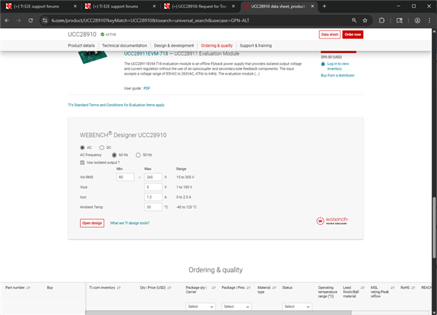
    First in the product page you can find a Webex design tool.  You just enter the input and output power requirements and the tool will generate a schematic and BOM.  You can compare this schematic and transformer connections to your design.

    https://www.ti.com/product/UCC28910?keyMatch=UCC28910&tisearch=universal_search&usecase=GPN-ALT


    The other option is to use the excel design tool that can be found at the following link.  It is similar to the Webench tool where you enter your input and output power requirements and it will calculate the electrical components you need for the design; as well as, calculate the transformer turns, currents and magnetizing inductance required for the design.  There is also a reference schematic that you can use to compare to your design.

    https://dr-download.ti.com/design-tools-simulation/calculation-tool/MD-BYW473Lu47/01.00.00.0B/sluc503b.zip


    There is an evaluation module for the UCC28910 and UCC28911 that you can order, evaluate and compare to your design.  It can be found at the following link.  A lot of customers find this evaluation useful in debugging their design.

    https://www.ti.com/lit/pdf/sluuai4


    Regards,


    Mike