This thread has been locked.

If you have a related question, please click the "Ask a related question" button in the top right corner. The newly created question will be automatically linked to this question.

TLV755P: Can I use TLV75533PDBVR for powering ADC

Part Number: TLV755P
Other Parts Discussed in Thread: TPS7A20L

Tool/software:

Dear team,

I will be using this ADC in my design.It has two power rails AVDD and DVDD.

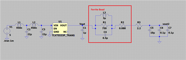
Two TLV75533PDBVR will be used one for AVDD and other for DVDD.

May I know this LDO is good choice for this ADC.If you can suggest other partnumbers it is appreciated.

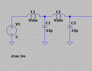
Before the input of the LDO.I will use a Filter as shown below near the power supply connector.

Regards

Hari

  • Hi Hari,

    The 755P should work for this application. Its current limit is sufficiently high, and you should be able to supply the device without hitting thermal shutdown. As for the design, it's usually best to place the ferrite bead before the LDO, not after, especially if the distance is short. How far away are you expecting the AD5490 to be from the TLV755P's?

    The filter is fine and should work. In my experience working with passive filters before an LDO, slightly higher capacitor ESR can improve the PSRR floor a bit. What effective PSRR are you trying to target?

    Best,

    Gregory Thompson

  • Hi Gregory,

    Thank you very much.

    In the reference design they used their own regulator very costly it's PSRR is 90 dB at 1 kHz, 60 dB at 1 MHz.

    How far away are you expecting the AD5490 to be from the TLV755P's?

    This is a test board I can keep LDO close to ADC.

    What effective PSRR are you trying to target?

    I don't know how to approach this.If you can give me some guidelines,that will be helpful for beginner like me.

    it's usually best to place the ferrite bead before the LDO, not after, especially if the distance is short.

    Thank you.May I know why.

    The filter is fine and should work

    May I know can I place ferrite bead after my 2nd order LC filter.

    Regards

    HARI

  • Hi HARI,

    Noise or ripple in the power supply will technically reduce the performance of the ADC and DAC inside the AD5941. I can't really speak to the performance quirks of their device, but I'd expect that to be your main concern. Some info on it from our ADC team: Caution! Your ADC may be only as good as its power supply - Precision Hub - Archives - TI E2E support forums

    PSRR is really just an (inverse) transfer function (that's why we publish it as a BODE plot), so your effective PSRR is just the product of your cascaded filters. So, the attenuation of any filters before or after it will add to the overall PSRR.

    A simple explanation is: Vout = DC_output + noise + PSRR*input_ripple. A filter before the LDO will filter out only ripple, a filter after the LDO will filter out both ripple and noise. But in my experience, the ripple voltage is usually already above the noise floor so there are minimal effects to putting it after, and then you're not fighting the parasitics and limitations of the ferrite bead on the output.

    You should be able to place the ferrite bead on your second order filter, but make sure there still is a capacitor directly connected to the input pin. As for passive filter design, parasitics are going to dominate at the upper region of the frequency range you're interested in (>~1MHz). I find this tool very useful for understanding capacitors in real world filters: Murata SimSurfing Tool (The curves themselves are mostly defined by the capacitor's rating).

    If you want closer performance, see if the TPS7A20L will work:

    TPS7A20L 300mA, Low-Noise, Low-IQ , High-PSRR LDO Voltage Regulator With 1.2V Logic Compatible Enable datasheet

    Lmk if you need any further help.

    Best,

    Gregory Thompson