

When it comes to the analog signal chain, everyone understands the importance of the input signal path. We design our systems to capture and preserve the integrity of signals of interest, while doing our best to block out or reduce interference. We pay careful attention to the selection of every component placed along the way…and then we just power it.
I once heard someone describe power supplies as “the shoelaces of electrical circuits.” Like circuits, a lot of hard work goes into the design and style of a shoe, but nobody thinks about the shoelaces until the end. While power supplies tend to be more of an afterthought, their design may be just as important as the signal chain itself.
In the first part of this series, I will introduce the concept of power supply rejection (PSR) and explain how power supplies can impact the performance of delta-sigma analog-to-digital converters (ADCs).
My DC power supply is “rock solid”… right?
Believe it or not, your power supply probably isn’t as solid as you think. From a DC perspective, both component tolerances and temperature drift can cause your supply output to vary from board to board and over temperature. A slight change may not seem important if it remains within your ADC’s operating conditions, but this may produce additional offset and gain error in the ADC transfer function.
Power supplies can also be quite noisy. Depending on their source or the surrounding environment, DC power supplies can carry an AC component as well. We are all familiar with the (figurative) headaches caused by 50 Hz/60 Hz power lines. Power-line noise often finds a way to couple in through lighting or nearby equipment, even for battery-powered applications. This noise may fall directly within your signal bandwidth of interest for some applications.
In addition, more complex systems can generate multiple power supplies from a single source using a switching DC/DC converter to “buck” or “boost” their source to another voltage. The frequencies of these switching power supplies may exist well beyond the signal bandwidth of interest, but these frequencies have the potential of aliasing back into the passband. This directly affects important AC specifications such as signal-to-noise ratio (SNR) and spurious-free dynamic range (SFDR).
ADCs expect a stable and purely DC supply, so any variation in that supply has the potential to change the ADC’s performance. Like most active components, ADCs are designed with some inherent immunity to power supply changes, but it is important to quantify whether this is enough for your application.
How susceptible is my ADC to its power supply?
ADC PSR describes the change in the ADC output relative to the change in its power supply. Sometimes it is specified as a ratio and referred to as the power supply rejection ratio (PSRR) expressed in decibels (dB). TI’s delta-sigma ADCs typically specify PSRR in two ways: PSRRDC and PSRRAC.
PSRRDC measures the ADC’s rejection of a DC shift in the power supply. To measure PSRRDC, you short the ADC inputs together and bias them to mid-supply as shown in Figure 1. Then, you power the analog ADC supply (AVDD) from a clean DC source and record the offset voltage at the output. As you increase or decrease the supply by 100 mV, record any change you observe in the ADC output. Figure 2 illustrates how the original offset voltage in the ADS1220 changes by 562 nV with a 100 mV change in supply voltage. Using Equation 1, PSRRDC is calculated to be -105 dB.

Figure 1: PSRRDC test setup

Figure 2: ADS1220 PSRRDC measurement
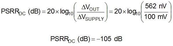
Equation 1
PSRRAC measures the ADC’s rejection of power-supply noise or ripple. To measure PSRRAC, you keep the ADC inputs shorted together and biased to mid-supply while adding a 100mVPP sine wave (VIN) to the DC power supply as shown in Figure 3. An AC signal generator with an offset voltage equal to the desired supply voltage will do the trick. For the frequencies of interest, you record the amplitude of the tone seen in the Fast Fourier Transform (FFT) of the output data and compute the PSRRAC using Equation 2. For the ADS1278, a 100 mV amplitude ripple translates to -28 dB from full-scale with a 2.5 V reference voltage and 24 bits of resolution. If this supply ripple has a frequency of 60 Hz, the ADS1278 will attenuate the ripple by another -80 dB, lowering the output magnitude at 60 Hz to -108 dB. Datasheets usually provide the PSRRAC specification for 50 Hz and 60 Hz in the electrical characteristics table and for all other frequencies in a typical characteristics plot up to 100 kHz or 1 MHz.

Figure 3: PSRRAC test setup
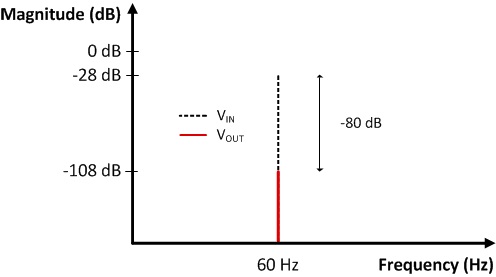
Figure 4: ADS1278 PSRRAC measurement
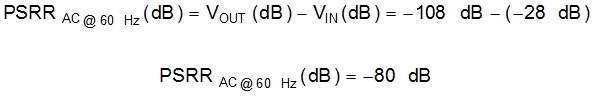
Equation 2
As I mentioned before, most ADCs have some level of PSR based on how they are designed. For those applications that require better PSR, the next post in this series will cover ways to improve PSR in your system.
In the meantime, check out other posts by my colleagues with design tips and delta-sigma ADC basics.
Additional resources:
Search TI’s precision ADC portfolio, including ADCs like the ADS1220 and ADS1262 for temperature measurement and programmable logic controller (PLC) applications.
Browse the all-new TI Precision Labs for a refresher on other analog design topics with over 30 hands-on trainings and lab videos.