


Tool/software:
Dear Team,
We are currently working on a flyback converter design using one of TI’s flyback controller ICs. We have received the transformer (T2) from our magnetic component manufacturer, and it meets our electrical specifications. However, we require assistance in correctly identifying which physical pins of the transformer correspond to the primary, auxiliary, and secondary windings as per TI’s flyback converter topology.
We tested the circuit on our board and observed the following:
-
12V is successfully obtained at the secondary output.
-
No voltage is appearing at the auxiliary winding output.
-
We suspect a mismatch or misconnection in the transformer pinout.
-
The transformer winding details (turns ratio) are clear, but pin mapping needs clarification.
We want to ensure proper connections and avoid layout or wiring mistakes. Kindly help us identify the correct transformer pin assignments, primary, auxiliary, and secondary,y based on the datasheet and schematic.
Schematic and Manufacturer Data are attached.
Your support will help us proceed with a reliable implementation.
Best regards,
Saif Shaikh 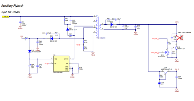
![]()