Tool/software:
Hello,
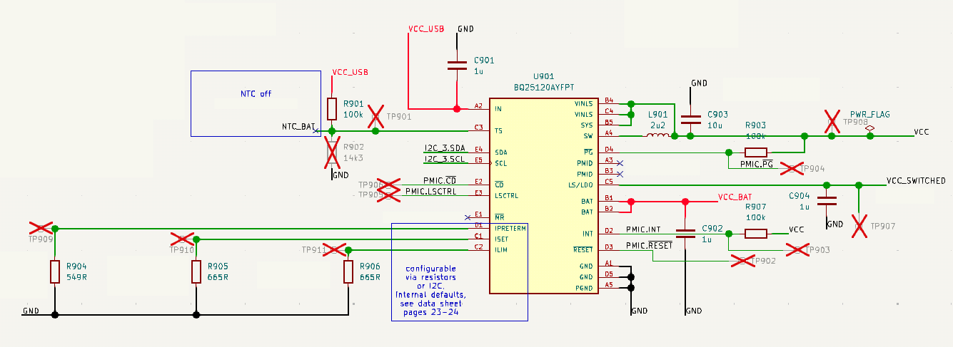
I have an application where the BQ25120A charges a battery and supplies power to part of the system, but other parts are powered directly by VBAT. Those other parts are LED drivers which need more current than the BQ25120A can provide which is why they are not connected to SYS, but directly to VBAT.
To my understanding this should not affect the BQ25120A (apart from VBAT not being the true battery voltage), but I am noticing some strange behavior when the current drawn on VBAT is high:
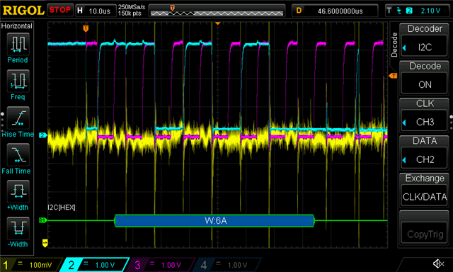
- When reading the battery voltage monitor I get 0x80, but only after a while. The readings are more or less correct for some time (much longer or always when the current draw on VBAT is lower) and then turn to 0x80 constantly (no more correct readings). At about 370 mA (current drawn from battery for the whole system), the readings are okay for about 30 s before they fail.
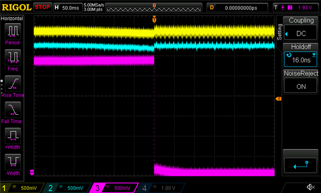
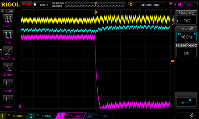
- SYS is shutting down (and reactivating). At 500 mA SYS starts to fail (off for ca. 400 ms, then on again for often about 2 s, but the on period varies a lot, sometimes less, sometimes a lot more).
- LS/LDO stops working reliably. Starting at around 250 mA, the voltage on LS/LDO, when turned on via LSCTRL, turns on and off unreliably and at a higher load does not turn on at all anymore.
Is there an explanation to how this could affect the chip's behavior and other things I would need to expect when using it in this kind of application?