This thread has been locked.

If you have a related question, please click the "Ask a related question" button in the top right corner. The newly created question will be automatically linked to this question.

BQ24193: Design Validation

Part Number: BQ24193

Tool/software:

Hi Team,

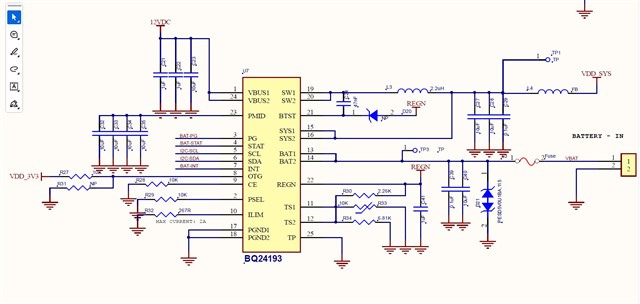
Please validate the attached circuit, here i have used 12V as input to BQ24193 to act as a power part + if no input it should work with Battery Input. I want to understand that if the input is 12VDC what is my VSYS voltage with battery and without battery. Any register need to be set for VSYS voltage over I2C?

Also please check the OTG configuration.. What is the default configuration for my requirement?

ILIM configured 2A

what will be the VSYS Load Current if my input is 12V

Regards

Srinivas

  • Hi Srini,

    First on your questions, if the device in powered by VBUS, and there is no battery load the device will regulate VSYS to the VREG voltage. With a battery it will depend on the battery voltage and some of the settings in your registers. In constant current mode the charger will continuously alter VSYS to achieve the set charger current. You can however set a VSYS_MIN (default 3.5V) when voltage needed to achieve the set charge current is bellow this value, the BATFET will act as a Linear regulator to ensure a controlled charge current while keeping the SYS voltage above VSYS_MIN.

    For OTG configuration do you mean hardware or register settings?

    The load current is not dependent on input voltage.

    Schematic Review

    1. the 22uF of Capacitance on VBUS is likely more than what is actually needed. 1uF is recommended.
    2. they may be included in another schematic but pullup resistors are needed for pins 3-7
    3. Note that for the ILIM pin the actual current limit will be set by the lower of what is set by the resistor and what is set by the registers so make sure to set your registers properly.
    4. I see it is indicated as NP but the diode on BTST is not needed
    5. I see that the bias resistors for the thermistor are set the values from the Datasheet, please not that those values are specifically for use with the 103-AT thermistor, if you are using a different thermistor you may have to change this.

    Lastly I am not sure what the loads of you device are or the EMC requirements but sometimes placing a ferrite bead on a power rail for digital loads can do more harm than good in terms of EMC. This article may be helpful.

    https://resources.altium.com/p/how-use-ferrite-bead-your-design-reduce-emi

  • Hi,

    There's no update for a while. The thread is considered resolved and closed.

    Thanks,

    Ning