This thread has been locked.

If you have a related question, please click the "Ask a related question" button in the top right corner. The newly created question will be automatically linked to this question.

TPSM82866A: Peripheral Circuit for Forced PWM Mode

Part Number: TPSM82866A

Tool/software:

Peripheral Circuit for Forced PWM Mode

I want to use forced PWM mode with a 3.3V Fixed output.
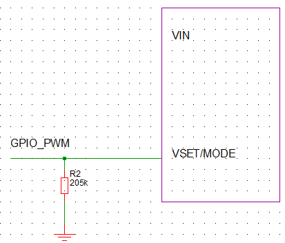
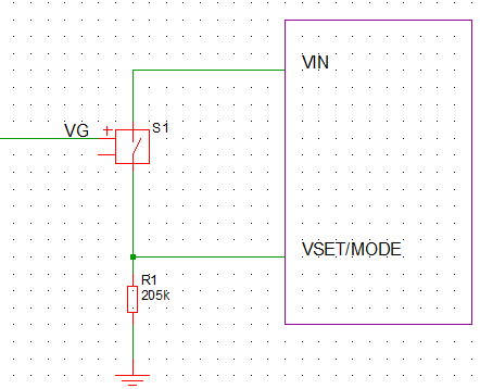
The VSET/MODE pin
(1) Because I want a 3.3V output, it must be connected to GND via a 205kΩ resistor when the IC is powered on.
(2) However, because I want to use forced PWM mode, it must be set high.
→Is it okay to connect VSET/MODE pin to GND via a 205kΩ resistor aPeripheral Circuit for Forced PWM Mode.pdfnd also to the VOUT pin?

  • Hi Hiroki,

    The connection shown in the pdf you attached won't work. 

    When the device is enabled it reads the resistor connected to the VSET/MODE pin to determine the output voltage. Thereafter this pin is used only for setting PFM or FPWM mode. 

    If you have an MCU on your board, you can use a GPOIO to drive the VSET/MODE to high after startup. Alternative is to have a switch between VSET/MODE and VIN. This switch can be turned on for example with VOUT. You would have to make sure that VOUT is sufficiently discharged before a new power up so that the switch remains open during power up. 

    If these options won't work, you can consider using the adjustable output voltage option and have VSET/MODE connected high.


    You need to take care that the capacitance at the VSET/MODE pin is not greater than 30pF. Higher capacitances can affect the readout and lead to wrong voltages.

    Best regards,

    Varun

  • Hi Varun, 

    Thank you.
    As you suggested, I would like to change my plan to use "Adjustable output."
    Is the attached circuit configuration okay?

    - Connecting the VSET/MODE pin to VIN
    - Setting R1 and R2 to 450kΩ and 100kΩ
    *I would like to configure two R1 and two R2 in series. Is that okay?

    Best regards,

    Hiroki

    Peripheral Circuit for Forced PWM Mode and Adjustable output.pptx

  • Hi Hiroki,

    Yes this schematic will work. You can make R1 and R2 with 2 resistors each.

    Best regards,

    Varun