BQ25798: BQ25798 Not Working Properly

Part Number: BQ25798
Other Parts Discussed in Thread: CSD,

Tool/software:

Hi Team,

We are using BQ25798 2s battery charging (7.4v 1200mAh), we are connected 5V/2A adapter. the BQ25798 is in default mode and the host device stm32 is only interface for getting battery voltages from ADC only when I power ON the device.

Sequence 1 :-mode sequence when device is turn ON and BQ25798 is charging (REG_RST reset(9h)->stop watchdog timer(10h)-> enable ADC(2Eh)->read ADC value(3bh) for battery voltage in 2sec timer)

Sequence 2 :-host mode sequence when device is turn OFF and BQ25798 is charging (REG_RST reset(9h)->Enable watchdog timer(10h))

issues:

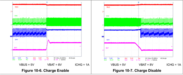
1)Condition when BQ25798 is in autonomous mode or default Note when we connect i.e. replace (6.65v) battery and I don't power the host, the battery gets charge successfully at 8.4v and state led turn off indicating charging complete. But when I replace new battery (6.65v) and restart charging sometime the battery doesn't charge even the state led is also on continuous.   

2) Condition when BQ25798 is charging in autonomous mode or default and I turn ON (Sequence 1) the host check the ADC battery voltage value and power OFF (Sequence 2) the host, the battery charging stops, but state led remains on.

3)While continues testing with above 2 conditions my  BQ25798 gets damage and vsys shows 0V even my battery voltage is 8V.

4) What is actual voltages of below pins on default condition when charger connected or charger disconnected (TS , ILIM_HIZ, REGN, PMID, BQ STAT PIN NO 1).?

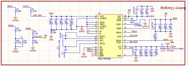
5)Also check if there should be any modification in the schematic. also suggest us if NTC and CSD is required or not.

Please help us with resolving issue.

Thank you.

I hope you will resolve all my queries? 

  • Hi Niketan,

    For 1 and 2, can you reply back with the status and fault registers in REG0x1B-0x27, as well as REG0x0F and ADC when this issue occurs?  Keep in mind the fault registers clear after being read.

    For 3, On the damaged IC without power, can you use a DMM set to resistance to measure the SYS, BAT, SW1, SW2, PMID, VBUS and REGN resistance to ground?  

    For 4, TS and ILIM_HIZ are pulled up to REGN.  When power is applied at VBUS, REGN should be ~5V. PMID=VBUS in charge mode.  STAT pin is low when charging, high Z when not charging and flashing at 1Hz when there is a fault.

    For 5, I do not see any obvious issues other than the ferrite beads. Is F1 on SYS node a ferrite bead?  Is it really only rated for 500mA? Is FB1 really 220ohm?  If NTC is not needed, TS function can be hardware disabled by using same sized resistor divider from REGN to TS  to GND. If by CSD you mean input MUX FETs then no.

    Regards,

    Jeff

  • Dear Jeff,

    Thank you for quick response,

    As per your instructions, register details are follows,

    Condition 1: - HOST ON (Charger disconnected)    

    REG 0X1B: 0X00

    REG 0X1C :0X00

    REG 0X1D: 0X01

    REG 0X1E: 0X00

    REG 0X1F: 0X00

    REG 0X20: 0X00

    REG 0X21: 0X00

    REG 0X22: 0X00

    REG 0X23: 0X00

    REG 0X24: 0X00

    REG 0X25: 0X00

    REG 0X26: 0X00

    REG 0X27: 0X00                                

    After 40second REG 0X1B : value change 0X00  to 0x20  

    Condition 2: - HOST ON (Charger Connected)    

    REG 0X1B: 0X2F

    REG 0X1C :0X6A

    REG 0X1D: 0X01

    REG 0X1E: 0X00

    REG 0X1F: 0X00

    REG 0X20: 0X00

    REG 0X21: 0X00

    REG 0X22: 0X80

    REG 0X23: 0X00

    REG 0X24: 0X00

    REG 0X25: 0X00

    REG 0X26: 0X00

    REG 0X27: 0X00 

    Condition 3.1: - HOST ON (When Charger unplugged) 

    REG 0X1B: 0X20

    REG 0X1C :0X00

    REG 0X1D: 0X01

    REG 0X1E: 0X00

    REG 0X1F: 0X00

    REG 0X20: 0X00

    REG 0X21: 0X00

    REG 0X22: 0X5F

    REG 0X23: 0X00

    REG 0X24: 0X00

    REG 0X25: 0X00

    REG 0X26: 0X00

    REG 0X27: 0X00 

    Condition 3.2:- HOST ON (When Charger unplugged after few second condition) 

    REG 0X1B: 0X20

    REG 0X1C :0X00

    REG 0X1D: 0X01

    REG 0X1E: 0X00

    REG 0X1F: 0X00

    REG 0X20: 0X00

    REG 0X21: 0X00

    REG 0X22: 0X00

    REG 0X23: 0X00

    REG 0X24: 0X00

    REG 0X25: 0X00

    REG 0X26: 0X00

    REG 0X27: 0X00 

     Damaged IC without power DMM set to resistance to measure the SYS, BAT, SW1, SW2, PMID, VBUS and REGN resistance to ground

    SYS: - 1ohm

    BAT: - 250ohm

    REGN: - 11. Kohm

    SW1: - Short 

    SW2: - Short 

    Observed voltages HOST on charger connected  

    SYS: - 6.8V

    BAT: - 6.95V

    REGN: - 5.3V

    PMID: - 5.0V

    ILIM_HIZ: -2.2V

    TS: - 3.1V

    Observed voltages HOST on charger disconnected


    SYS: - 6.9V

    BAT: - 6.9V

    REGN: - 2.73V

    PMID: - 4.17V

    ILIM_HIZ: -2.2V

    TS:- 3.13V

    for point no5 F1 on SYS is PTC for for protection purpose we added.

    Is FB1 really 220ohm? it is 220ohm & 2Amp supported.

    We observed some conditions (Registers)

    First, we plug the charger note down register address (charging led on but not charging)

    REG 0X1B: 0X0F

    REG 0X1C :0X6A

    REG 0X1D: 0X01

    REG 0X1E: 0X00

    REG 0X1F: 0X00

    REG 0X20: 0X00

    REG 0X21: 0X00

    REG 0X22: 0X00

    REG 0X23: 0X00

    REG 0X24: 0X00

    REG 0X25: 0X00

    REG 0X26: 0X00

    REG 0X27: 0X00 

    Then unplug the charger & plug it again then we observed 

    REG 0X1B: 0X0F

    REG 0X1C :0X6A

    REG 0X1D: 0X01

    REG 0X1E: 0X00

    REG 0X1F: 0X00

    REG 0X20: 0X00

    REG 0X21: 0X00

    REG 0X22: 0X00

    REG 0X23: 0X90

    REG 0X24: 0X40

    REG 0X25: 0X00

    REG 0X26: 0X00

    REG 0X27: 0X00 

    after we again unplug the charger & plug it again 

    REG 0X1B: 0X2F

    REG 0X1C :0X6A

    REG 0X1D: 0X01

    REG 0X1E: 0X00

    REG 0X1F: 0X00

    REG 0X20: 0X00

    REG 0X21: 0X00

    REG 0X22: 0X02

    REG 0X23: 0X0

    REG 0X24: 0X40

    REG 0X25: 0X00

    REG 0X26: 0X00

    REG 0X27: 0X00 

    what should i do because we not get same condition again, we get different address but led still remains on & battery could not get charge.

  • Hi Niketan,

    The damaged IC has several pins shorted to GND.  Other customers have seen either SYS, BAT and sometimes SWx shorted to GND if fully charged 4S battery (16.8V) is hot plugged.  

    Regarding the 40s reset, the WD timer resets registers to default if not disabled or no period writes to the WD bit.

    I do not see any other issues with the registers.

    Do you have a BQ25798EVM to test with?

    Did you follow the datasheet layout recommendation?  This device is very sensitive to board layout.

    Regards,

    Jeff

  • Hello jeff, 

    As per my observation when our device is OFF & I plug the charger the device charges the battery from 6.5v to 8.4v within 3 to 3.5hrs in autonomous charging (default)

    But same condition when I turn on the device (MCU on HOST) while charging the battery charging stops frequently, is it because of it goes into HOST mode & never return back to autonomous mode??

    When HOST is ON my Timer every 2sec interval is calls (ADC Enable & ADC read Value) other than this register i don't changes any value of IC

    We have tested on Development board link as below mentioned

    USB-PD-CHG-EVM-01 Evaluation board | TI.com

     Did you follow the datasheet layout recommendation?  YES, we follow all recommendation as per datasheet 

    We are only Few additions of circuit as see above attached schematic VSYS terminal PTC add (PSMF050X-2 0.5A 6V 500MA) for protection,

    instead on NTC we add 10k fixed resistor R11.

  • Hi Niketan,

    If WD timer is enabled, the charger exits host control (reset all registers to defaults) if the WD timer does not have a write in the specified time.  

    Can you re-test after shorting out the fuse?

    Regards,

    Jeff

  • This waveform is from the BQ25798 datasheet.

    this image from BQ25798 Datasheet.


    In the above video:

    CH1-SW2 & CH2-SW1

    When the MCU is ON & then we connect the charger for the first time, at that time SW1 & SW2 switches correctly & the battery starts to charge. But if we disconnect & connect the charger 2nd time , then charging will stop.
     

    Also, when we charge the battery in the MCU off condition, then the battery charges correctly.


  • Hi Niketan,

    What do the status and fault registers in REG0x1B through REG0x27 as well as REG0x0F report at this time?

    Regards,

    Jeff