This thread has been locked.

If you have a related question, please click the "Ask a related question" button in the top right corner. The newly created question will be automatically linked to this question.

BQ25750EVM: The charging issue with the BQ25750

Part Number: BQ25750EVM
Other Parts Discussed in Thread: BQ25750,

Tool/software:

Hi,


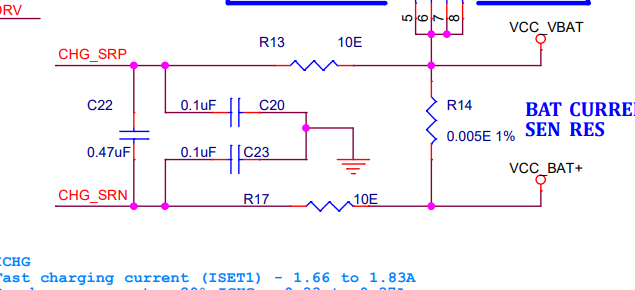
We designed a PCB using the BQ25750 charger IC (similar to the BQ25750EVM) to charge a 4S1P LiFePO₄ battery. The charging current is set to 1.8A, and the full charge voltage is 14.6V.

Issue:

  • The battery is not charging properly.
  • Charging current is very low (only 8–25 mA).
  • Output voltage at battery terminal 12.85V (same as battery voltage when the battery is connected).
  • Output voltage at battery terminal 7.05(when the battery is not connected).
  • No change in voltage or current even after 15 minutes.
  • STAT1 is ON, STAT2 is OFF (indicating charging in progress) when the battery is connected.
  • No changes made to default register settings.

Setup:

  • Battery voltage during testing: 12.85V 
  • Input voltage (VIN): 12V
  • ICHG set as: 1.8A
  • ILIMIT set as: 10A
  • Actual load during this testing: < 0.5A
  • Buck boost Fsw: 250kHz
  • Driver: Internal LDO
  • CE pin: LOW (charger enabled)

Please help us identify and fix the issue.

Thank you

  • Hi,

    FYI, Battery charger status registor showed fast charging in cc mode

  • Hello Jeevabharathi,

    Thanks for being patient with this. I'll get to your question tomorrow.

    Best Regards,
    Ethan Galloway

  • Hello Jeevabharathi,

    Can you answer a few questions to help us debug this?

    • What's the register settings of the BQ25750?
    • Can you measure SW1 and SW2 with an oscilloscope? Are these signals switching?
    • Can you measure the voltage on the VAC and VSYS pin while the battery is connected?
    • Can you measure the voltage on FB pin when the BQ25750 is charging? FB is a delicate pin. I recommend turning the charger OFF, connecting the oscilloscope or voltmeter to FB, and then turning the charger ON.
    • Do you know what the battery gauge is in the battery?

    Best Regards,
    Ethan Galloway

  • Hi  

    We have done few changes

    1. Bootstrap C12(EVM) and C18(EVM) changed from 1nF to 100nF

    2. 10K thermistor connected.

    Our circuit is now charging the battery with a plused current of 2.56A (ICHG set - 1.8A).

    Kindly share your thoughts on how to solve this pulsed current?

    Attached the image for your reference.


    Charging current is pulsed at 15.15KHz at 2.56A

    Attached the schematics for your reference. Please review and share your comments.

    2376.BQ2575 Schematics.pdf

    Please find the answer to your queries.


    1. What's the register settings of the BQ25750?

      It is the default value mentioned in the datasheet.

    2. Can you measure SW1 and SW2 with an oscilloscope? Are these signals switching?

        Yes, SW1 and SW2 are switching. please find the image

    3. Can you measure the voltage on the VAC and VSYS pin while the battery is connected?

          VAC is 12.21V

          VSYS is 12.2V

    4. Can you measure the voltage on FB pin when the BQ25750 is charging? 

          VFB is 1.445V

    5. Do you know what the battery gauge is in the battery?
    We are testing the battery without fuel gauge but with the 10K thermistor connected.

  • Hello Jeevabhrathi,

    .

    1. What's the register settings of the BQ25750?

      It is the default value mentioned in the datasheet.

    Can you provide a register dump when this behvior occurs? I want to see what the registers read, not what is written by the host.

    Best Regards,

    Christian.

  • Hi  

    We implemented the following changes and now the current ripple reduced from 1.9A to 0.25A. 

    Added an RC (1.8K and 0.1uF) parallel to ICHG resistor.

    However, when charging the battery using EVM (same resistor restting ICHG) the ripples is only 50mA, whereas in our charger design the ripple is around 0.25A.

    Could you please advise on what further modifications we can make to reduce the ripple to below 50 mA?

  • Hello Jeevabharathi,

    Did you place the BATSNS filtering caps as close as possible to the IC? Can you confirm you followed to PCB layout guidlines to run the sense lines a differential pairs?

    Best Regards,

    Christian

  • Hi  

    In our current board revision, the charger sense lines are not routed as differential pairs. Given this limitation, is there any way we can further reduce the current ripple?

    Additionally, we've observed a difference in behavior between our design and the EVM. On the EVM, the STAT pin transitions correctly from "charging" to "charge done" at the end of the charging cycle.

    However, in our board, the STAT pin switches from "charging in progress" to "charging fault detected", and the "charge done" status is never reached, even after leaving the system running for several hours.

    Could you help us understand why this might be happening and suggest any possible solutions?

    Thanks,

    Jeevabharathi

  • Hello Jeevabharathi,

    In our current board revision, the charger sense lines are not routed as differential pairs. Given this limitation, is there any way we can further reduce the current ripple?

    Can send me a picture of the battery current sense lines so I can see what this looks like?

    Could you help us understand why this might be happening and suggest any possible solutions?

    Can you take an oscilloscope image of VBAT? This will help me see what's going on.

    I have a few suggestions to help the charger terminate:

    • Can you set EN_PFM=0?
    • Does increasing the termination current improve the behavior?
    • Does decreasing the charge current improve the behavior?

    Best Regards,
    Ethan Galloway

  • Hi Ethan,

    Thank you for your suggestions. I’ll implement your comments and share the results with you by the end of the day..

    We’ve started investigating the issue and have a few updates to share:

    • We checked the battery register status and observed that the Battery Over Fault bit is set to 1.
    • Please find the attached register dump for your reference.
    • We’ve also included the VBAT voltage and battery current readings for your review.

    I’d appreciate it if you could share your thoughts on this.


    Thank you!

  • Hi Ethan,

    The charging process is now functioning correctly after setting EN_PFM = 0.

    The STAT pins are indicating a successful charge completion, and no charging faults have been observed.

    Thank you for your support! We are currently verifying the other functionalities of the battery charger and will reach out if we need any further clarification.

    Thank you.

  • Hello Jeevabharathi,

    That's great to hear! Your welcome. Let us know if you have any other questions about this.

    Also, we generally recommend setting EN_PFM=0 when the termination current is below 2A.

    Best Regards,
    Ethan Galloway