TPS65131: Noise issue on dual DC/DC converter (Load current waveform)

Part Number: TPS65131
Other Parts Discussed in Thread: PGA855, INA823, PGA855EVM

Tool/software:

Hi Patrick,

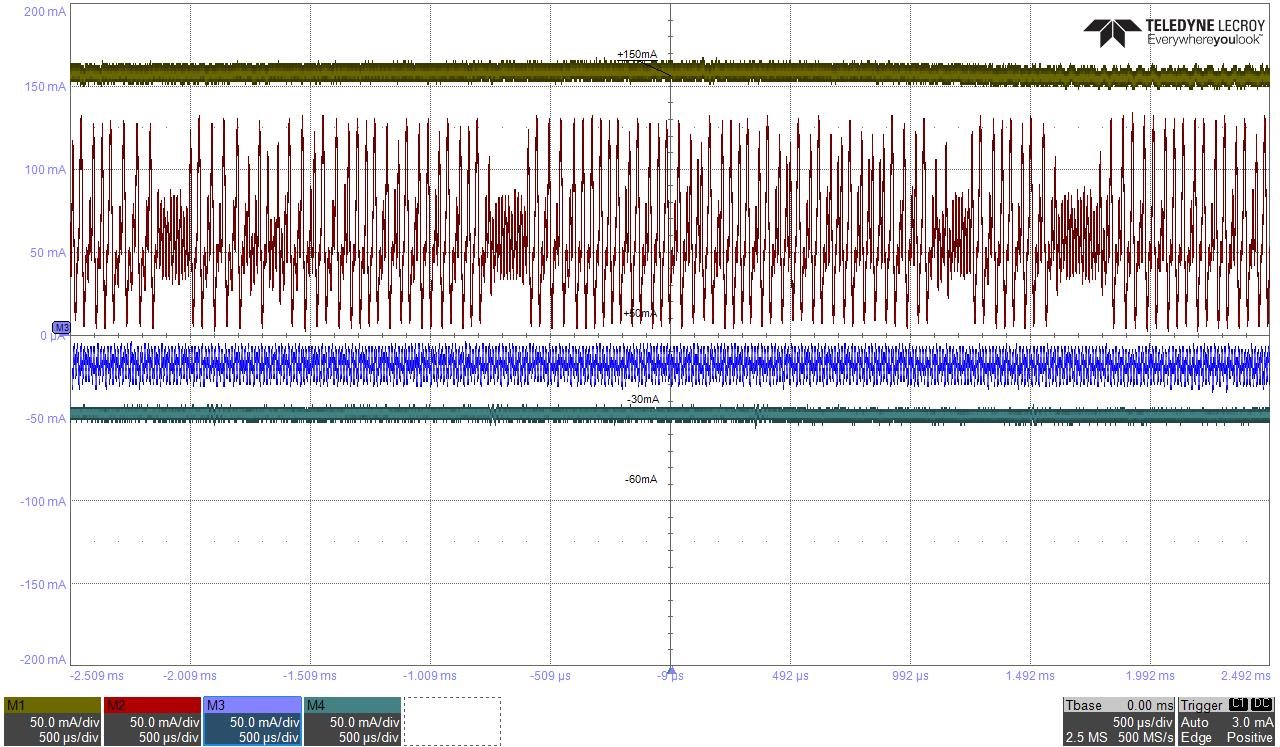
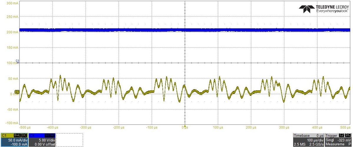
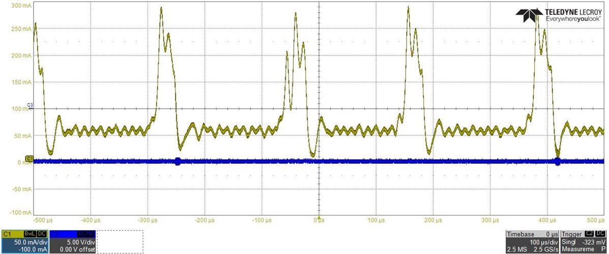
I apologize for reviving the old post now ( TPS65131: Noise issue on dual DC/DC converter ). I measured the current across resistors R118 for VCC and R117 for VEE.

When I removed R117, the whistling sound was no longer heard. The two traces are actually different, with current spikes of up to almost 300mA on the negative -10V generation.

Regarding the voltages, as you can see they are stable, which is why I didn't add any more bulk capacitors.

VCC

VEE

Do you have any suggestions for solving the initial whistling problem?

Thank you for your support.

Salvatore.

  • Hi Salvatore,

    Is the TPS65131 supplying a display? If so, the current load might be related to the display pattern.

    BR

    Patrick

  • Hi Patrick,

    The TPS65131 does not power a display but a PGA855 (VCC and VEE) as shown in the following image.

    In any case, I can't explain the current flow for VEE, which is probably the cause of the noise.

    I look forward to hearing from you.

    Regards,

    Salvatore

  • Hi Salvatore,

    I am not so familiar with the FDA, but maybe you could check whether the IN-, IN+ and VOCM of the PGA855 are stable or not first.

    And for the INA823, what are the voltage of IN- and IN+? And is the output of INA823 stable or not?

    Since TPS65131 is the power supply to the FDA, so the pulse current load is very likely related to the amplifier operation. If you have already captured any waveforms of the amplifier circuit, please let us also have a look, thanks.

    BR

    Patrick

  • Hi Patrick,

    IN- and IN+ are the signal inputs from the BNC. A 50-ohm cap was used for testing. I can confirm that the VOCM is stable at 1.75V. The INA823 output is always 0V because, as mentioned, the input is 0V.

    Meanwhile, I ran some tests:
    - I powered the TPS65131 with an external 5V supply (across C163) -> no change with noise.
    - I powered the circuit after the PGA855 with external +10V/-10V VCC/VEE (removing R118 and R117) -> it works correctly as per the PGA855EVM evaluation board, where each branch draws less than 20mA.
    - I reinstated the internal power supply, removed the PGA855, and connected a 120-ohm linear resistive load -> no whine.
    - From the previous condition, I limited the current of the 5V input to 500mA -> the whine reappeared.
    - From the previous condition, I removed the current limit and resoldered the PGA855 -> the whine is still present.
    - I connected the +10V/-10V output from my board to the PGA855 evaluation board -> the whistling noise is present, behaving like my board.
    - I removed the ferrites between the power supply and the load, but the noise/interference on the current has increased.

    So I don't think that the problem is in the downstream circuit, since I have no problems with an external power supply.

    Regards,

    Salvatore

  • Hi Salvatore,

    When you did the "I powered the circuit after the PGA855 with external +10V/-10V VCC/VEE (removing R118 and R117) -> it works correctly as per the PGA855EVM evaluation board, where each branch draws less than 20mA.", have you captured the current waveform of +/-10V?

    BR

    Patrick

  • Hi Patrick,

    yes, I captured it with the oscilloscope: the current waveform is stable in this condition without noise.

    Regards,

    Salvatore

  • I ran further tests, of which I'm attaching a screenshot from the oscilloscope.

    I replaced the PGA855 with an ITECH IT8511A variable load and noticed that the current behavior is "strange" for low values: the positive branch has a linear current trend after 130mA, while the negative branch has a linear current trend after -50mA. For lower values, however, noise is present on both the oscilloscope and the whistling sound.

    Regards,

    Salvatore

  • Hi Salvatore,

    I will give you feedback later.

    BR

    Patrick

  • HI Patrick,

    any news about that?

    Regards,

    Salvatore

  • I will give the feedback tomorrow

  • Hi Slavatore,

    Are you able to connect PSP and PSN to GND to disable the power save mode?

    BR

    Patrick

  • Sorry Patrick, but did you see my original post? There's the electric diagram with connections.

    This is a very important project for me and we can't find a solution for this problem. Why the component produced by Texas Instruments is not working properly?

    Regards,

    Salvatore

  • Hi Salvatore,

    Based on your waveforms, I suspect the audible noise is caused by the light load in power save mode. In this mode, IC will skip some switching cycles to reduce the power loss, but it may have chance to cause the converter works in audible frequency range. Is it able for you to add more loading to make the IC quit the power save mode?

    BR

    Patrick

  • Hi Patrick

    After some tests and carefully reviewing the schematic, your suggestion solved the problem.

    Thank you very much for your time.

    Regards,
    Salvatore

  • Hi Salvatore,

    Thanks, good to know the issue is resolved. You can disable the power save mode in your future design.

    BR

    Patrick