LMR36503-Q1: Incorrect output of the fixed 3V3

Part Number: LMR36503-Q1

Tool/software:

Hello,

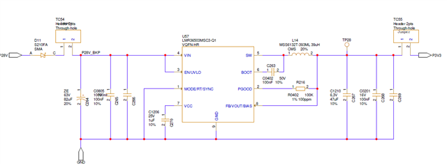
We have implemented the LMR36503MSC3 in our design.

The schematic is the following :

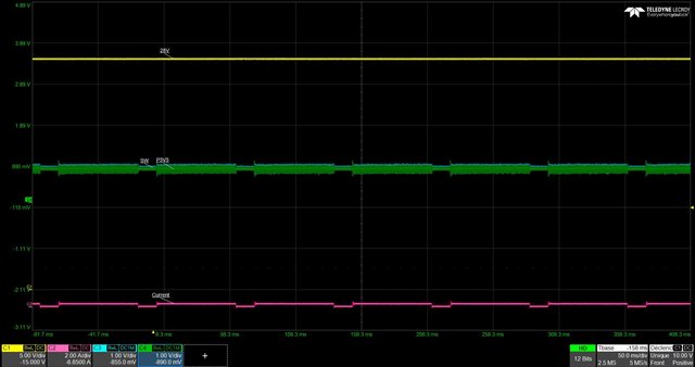
However, when applying 28V on the TC54, the component does not output a 3V3 voltage as we would expect.

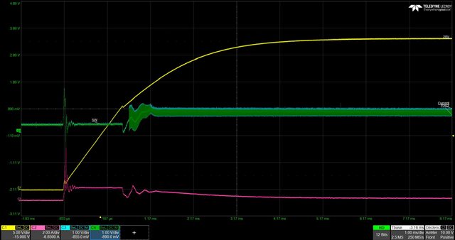
The voltage on the SW output is not as expected either and it seems like the component is trying but is unable to switch.

Here is an oscilloscope copy from the startup:

And afterwards once the 28V is established:

Any idea of the issue ?

Thank you,

Best regards

C. Letonnelier

  • Hi Clement, 

    Your device is in standby/shutdown because your enable pin is low, also your RT pin is floating (device won't switch). Your actual design has a lot issues used this Design calc to help you with your measurements and design. LMR36503E-Q1_calc.xlsm

    Thanks.

  • Hello,

    Why do you say that ?

    we are injecting 28V on the pin 2 of TC54 for test purpose.

    rt is connected to ground so not floating.

    Best Regards

    clement

  • Hi Clement, 

    I check your design please ensure the following: 

    C226 is a 2.2uF ceramic and Your inductor L = 10uH. This ensures stability. 

    Reviewing your waveforms I'm not sure what I'm looking at. Please confirm the following:

    CH1 = Vin?, CH2 = Iout?, CH3 = Vout, currently at about 1V (not 3.3V), CH4 = SW?

    The switch node should be switching between Vin and GND at a duty cycle of Vout/Vin. I do not see this and therefore, there might be a problem with the device.

    Have you tried swapping it out?

    Lets us know if you have made the above design changes/swap out the device and you still have issues. 

  • Hi  Tony

    I'm replacing Clément who is on vacation this week.

    Waveform

    Yellow Curve (Vin_nom=28V and Vinçmin=10V & Vinmax=60V)

    Red Curve (Current. Imax =150mA)

    Green Curve: (Vout=3.3V)

    Blue Curve ( Pin 5)

    I confirm the switching node does not switch

    The diagram as is already worked on another board

    We haven't changed the controller yet

    On the other hand, I also propose to introduce a resistor on RT to reduce the frequency because in our conditions of use the component would heat up too much (Tamb=70°C). So we are thinking of putting a resistor to be at 900kHz of Fsw

  • Hi Pascal, 

    Yes i encouraged you to use the RT variant. Just know that the variant you're using isn't the RT version. Here is a list of device that are RT variant and Mode/SYNC variant. 

    Also, make used of this calculator LMR36503E-Q1_calc (1).xlsm