TPSF12C1: The performance of CM has improved, while that of DM has deteriorated.

Part Number: TPSF12C1

Tool/software:

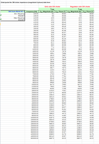
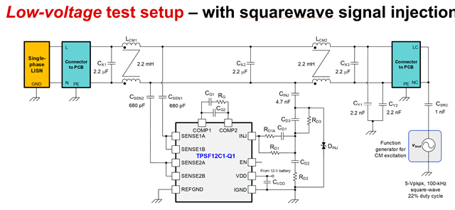
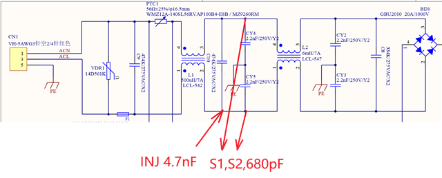
The TPSF12C1 is used to test the following filter circuit. The circuit and connection method are as shown in the figure below:

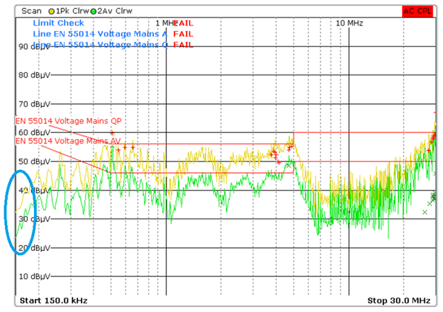
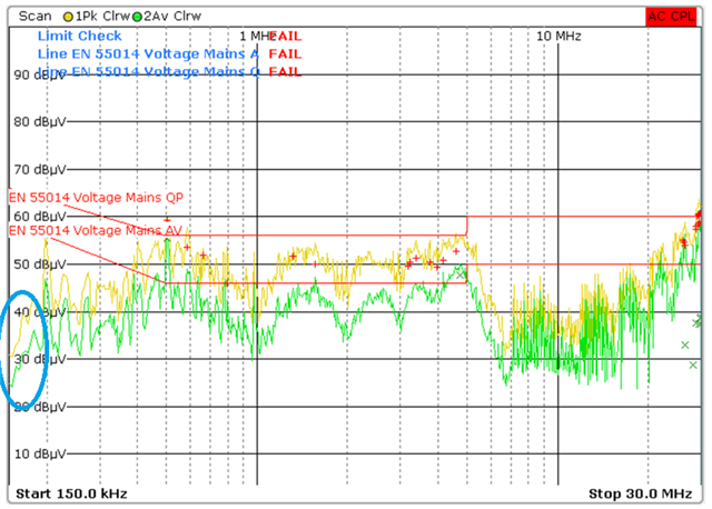
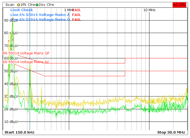
DM test results without TPSF12C1 circuit

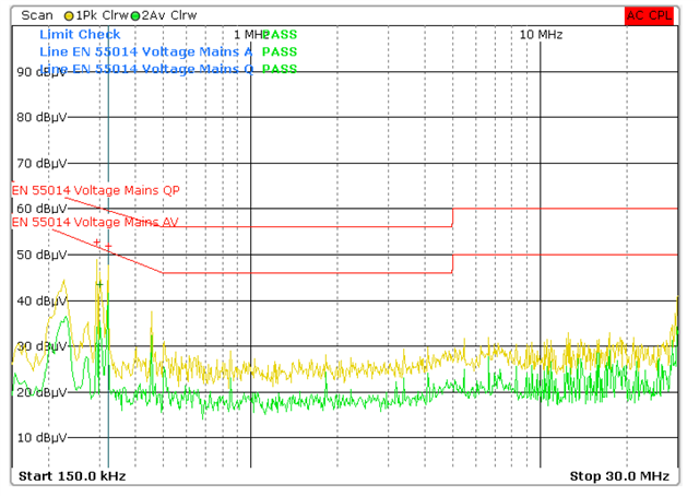
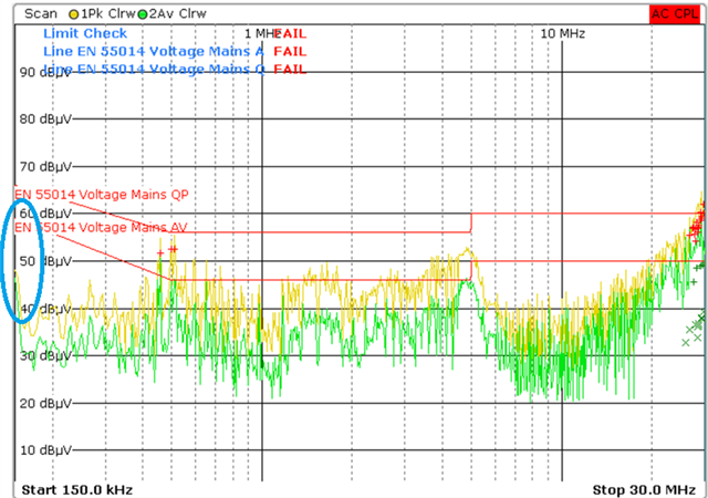
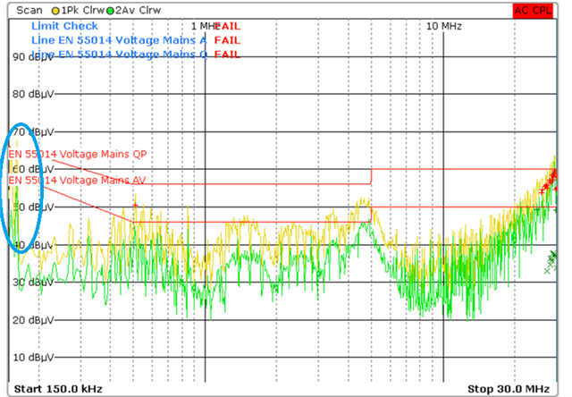
DM test results with TPSF12C1 circuit

The X capacitor and CM coil remain unchanged, with only the addition of the TPSF12C1 circuit. While the common mode noise has decreased, the differential mode noise has significantly increased. What could be the reason for this? Is there a way to address this issue?

  • Hello

    Thanks for your question. I will look into it and get back to you

    Thanks and Regards

    Naresh

  • Hello Hongxing,


    Could you please confirm what is the dominant noise in your system? Also, could you please confirm if it is a OBC system? What is the switching frequency?

    By definition, TPSF12C1 IC is designed to help or reduce with common-mode noise. It doesn't help with differential mode noise in the circuit. If the system is not completely CM dominant, then TPSF12C1 is not the right fit for your system.

    Thanks and Regards,

    naresh

  • Hello Naresh,

    The system is mainly affected by common-mode noise. When TPSF12C1 is not connected, the differential-mode noise is within the standard, but the common-mode noise exceeds the standard. The common-mode noise exceeds the standard at 500K, 5M, and 26M. This is not an OBC system, but a motor drive system. The switching frequency is 65K.

    According to the test results, after connecting TPSF12C1, the differential mode noise has deteriorated. Originally, the differential mode noise was within the standard, but after connecting TPSF12C1, it exceeded the standard by a large margin. I would like to understand the reason and how to solve it? If solving one problem brings about other issues, it would be unfavorable for my system.

    Thanks and Regards,

    Hongxing

  • Hello

    received your question. We will look into it and get back to you. 
    today is a holiday in India 

  • It is generally not recommended to use the TPSF12C1 device without first running an initial evaluation in the QuickStart calculator.

    Have you entered your system in the QuickStart calculator and verified whether the AEF loop is stable with AEF included?

    I’ve attached the tool—please enter your system parameters and share the results with us.

    In addition, we recommend configuring AEF with a balanced filter, where both Cm chokes have similar values for symmetry. This helps make the system easier to stabilize in AEF operation. We noticed that your current design uses 0.5 mH and 6 mH choke values.

    What are the values of your X-capacitors? Have you tried increasing them and observing the impact?

    Choke details: What type of chokes are used (Ferrite or Nanocrystalline)? Were they characterized by measuring impedance and phase across frequency? 

    Could you please let me know answers to these questions. 

    Thanks and regards

    Naresh 

  • Hello Hongxing, 

    I received your question. I will get back to you

    Thanks and regards,

    naresh

  • Hello Hongxing, 

    AEF is not recommended in the case where we have ferrite chokes and unbalanced choke values (0.5 mH and 6 mH choke values). It will not work in the system and doesn't realize a stable loop with AEF incorporated. 

    We recommend that only nanocrystalline chokes are being used and same values both for the grid side and regular side choke are needed.

    Also, as mentioned by you, the capacitances of the X-capacitors are 0.47 microfarads (μF), 0.47 microfarads (μF), and 0.33 microfarads (μF) respectively. These values are very low and usually we recommend using values of the order of 2 microfarads for X-capacitors. As you change the chokes, could you please also increase the X-capacitor values and check?

    Hope this information helps. Please check and let us know.

    Thanks and regards,

    naresh 

  • Hello Naresh,

    I will try it as you suggest and I will let you know when the results are available.

    Thanks and regards,

    Hongxing

  • Sure Hongxing. Check and let us know. 

    Thanks and regards,

    naresh

  • Hello Naresh,

    The capacitance is changed to 2.2u 0.47u 0.33u, and the common mode inductor is changed to 6mH 6mH, and the inductor is made of nanocrystalline material.

    The test results showed that the addition of active filters had no negative impact on DM interference. CM interference increases around 160K, causing L N to exceed the standard around this frequency.

    CM (no  active filters)

    CM ( active filters)

    L  (no  active filters)

    L (active filters)

    Thanks and regards,

    Hongxing

  • Hello Hongxing, 

    Could you please ask them to fill the quick start calculator for their existing system? That would help evaluate whether adding AEF with their passive filter will result in stable operation or not.

    Thanks and Regards,

    Naresh

  • Hello Naresh

    Since the existing instruments can only test the inductance up to 500k, I am afraid that the results have no reference value.

    Thanks and Regards,

    Hongxing

  • Hi hongxing

    thanks for your message. I will look into it and get back to you 

  • Hi Hongxing, 

    Could you please check with the vendor from where you got the chokes - if they can provide with the data or if you can get it measured elsewhere?

    500kHz is too less. The data is needed till 10MHz.

    Thanks and Regards

    naresh 

  •  Hello Naresh,

    The supplier and our company cannot find available equipment.can we assess the stability of AEF through the INJ waveform or other methods?

    Thanks and Regards

    Hongxing

  • Hi Hongxing, 

    It is not easily possible to evaluate stability using other methods. 

    One thing you can do to check the functioning of the AEF independently is by using low voltage test method as shown below

    Disconnect the OBC, use function generator input as shown here and measure the SENSE and INJ pin waveforms for the board that you are using.

    One more question: we don't recommend these devices for other than OBC systems right now. What is the total Y-capacitance budget for your system? Is this governed by a touch current specification? could you please let me know

    Also, could you please try above test method to evaluate functioning

    Thanks and Regards,

    naresh