BQ25820: Charging problems...

Part Number: BQ25820

Tool/software:

Hi,

We have designed a PCB with a single cell LiPo battery and a BQ25820 charger and also a BQ27441 gauge IC.

The charging doesn't seem to work though. Battery is 3.0 - 4V (3.7V nominal) 3000mAh. We use +12V as Vin and the schematic looks like this:

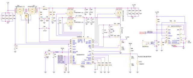
I cannot find why the charging doesn't start. Any suggestions?

B.R,

Leif Svensson

  • Hello Leif,

    The charging doesn't seem to work though. Battery is 3.0 - 4V (3.7V nominal) 3000mAh. We use +12V as Vin and the schematic looks like this:

    Can you provide a register dump when this behavior occurs?

    Best Regards,

    Christian.

  • Hi Christian,

    I don't have connection to the I2C bus at the moment. It will be available soon. However I saw that compared to the application schematic in the datasheet I lack a diode connected from the DRV_SUP to the BTST1 pin. Will that make any difference? I will test it soon, I just wanted your opinion on that.

    Best Regards,

    Leif S.

  • Hello again Christian,

    Just a quick update: With a schottky diode from DRV_SUP to  BTST1 the charging started! Battery voltage is right now 4.052V and rising. I use a DC power supply to feed into Vin. However, if I raise the input voltage slowly to 12V and above, the charging voltage is reducing and at 13V it stops completely. Why is that?

    I don't use any input voltage limitations, ACUV is connected directly to Vin and ACOV is connected directly to power GND. Could this cause any unwanted behaviour? I need the circuit to accept at least +12V.

    Best Regards,

    Leif S.

  • Thanks for posting. It was US holiday on Monday. A team member will look into this and get back to you tomorrow

  • Hello Leif,

    Can you check to see if the device is able to work without the guage?

    Best Regards,

    Christian.

  • Hello Christian,

    An update of the latest findings:

    We seem to have solved our problems! We had a couple of problems which we most probably have found and solved. First the insufficient charging at above +12V Vin, that problem was solved when using a better diode! The diode from pin DRV_SUP to pin BTST1 that I had missed at first, I changed it into a faster better diode with lower Vf and lower diode capacitance. That did the trick!. 

    Secondly we noticed that the circuit drained the battery when in idle. We found that the POWER GOOD signal was indicating a good input voltage even though we had turned off the power supply. This was because the battery itself kept the power rail high and since I didn't use any limits for OVER VOLTAGE or UNDER VOLTAGE the charger thought power was good and kept the incoming transistors open with a gate voltage of approx 15-20V. They never turned off. We tried to patch in adequate resistors to establish the OV and UV limits, but it was too difficult on our PCB. Instead we solved that by patching in a series diode just after the sense resistor on incoming power. That prohibited the "self holding" and the transistors were shut off. I want to point out that not using any OV or UV limits is a suggestion from your datasheet, but then this issue turns up! People should be aware of this phenomenon.

    Now the board can charge the battery properly and charging is turned off at a battery voltage of approx 4.2V as expected. When charging is ready the status pins indicate that it is ready. The power rail is powered correctly with either incoming voltage or the battery, also as expected. All is working good so far. We haven't been able to connect to the I2C just yet so the gauge circuit is still to be tested. Our software guys are working on this right now. However, our initial problems seems solved.