LP2998: LP2998 – Issue with Supercapacitor cell Charging / Balancing , VC Clamped at ~1.25 V

Part Number: LP2998

Tool/software:

Hello 

We are using the LP2998MR in a supercapacitor balancing application (2 × 3.3 F, 2.7 V supercaps ). Part of the circuit is based on TI reference design https://www.ti.com/tool/PMP9766#tech-docs 

The boards are powered from 5 V with current limited to 150 mA (requirement of the solution). 

  • In the 29 prototypes, 21 units work correctly and the supercapacitors charge up to the nominal voltage.

  • In 8 units, the supercapacitors do not charge: the VC voltage does not rise above ~1.25 V.

        Removing Q1 and Q2 did not resolve the issue.

        Replacing the LP2998 on failing units restored normal operation, with the supercaps charging and balancing correctly.

        The removed IC, when placed into a good board, reproduced the same failure.

  • Is there anything wrong in our circuit that could be damaging the IC  LP2998, or is this simply a case of defective devices ?

Thanks in advance

SUPERCAP BALANCING.pdf

  • Hi Paulo,

    Let me take a look at the schematic and get back to you tomorrow.

    Regards,

    James

  • Paulo,

    Can you try adding a 0.1uF capacitor to the VREF output on the failing boards?

    Unless the datasheet specifically says you can leave a pin floating, I would recommend following the suggested passive components.

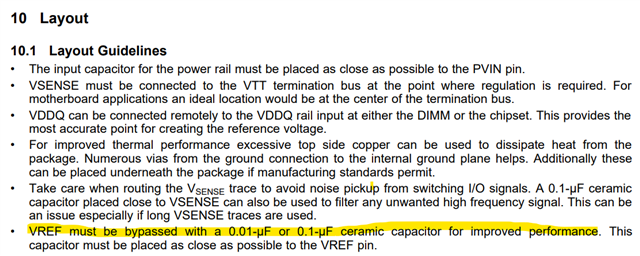
    Looking at the internal block diagram it doesn't immediately seem like the VREF should be necessary for device operation but if we look at the layout guideline we see VREF mentioned:

    Just based on this statement, it seems like the floating VREF might be an issue.

    However, if this doesn't solve the problem then I would recommend doing a customer quality return since I don't see anything else wrong with your schematic.

    Regards,

    James

  • Hi James 

    We tested another batch of 10 units, and in 2 units we observed the same issue (VC does not rise above ~1.2–1.3 V).
    As mitigation attempts: Added a 100 nF ceramic capacitor on VREF ,  no effect.
    Added a 100 nF capacitor on VSEN , no effect.
    Added an additional 22 µF in parallel with the decoupling capacitor on PVIN , no effect.
    These decoupling changes did not resolve the issue, We then replaced the LP2998 ICs on the 2 failing boards, and both became fully functional.

  • Hi Paulo,

    Just a couple of questions:

    • How were these LP2998 units acquired?
    • Can you share a picture of the top marking on a couple failing units? I might be able to request a quick look into any history of issues.

    Regards,

    James

  • Hi James

    The LP2998 ICs were purchased directly from Future Electronics distributor and from Ti direct

    r

  • Hi Paulo,

    Let me run these pictures by our team to see if there's any information on these.

    Regards,

    James

  • Sorry for the long delay Paulo,

    There's nothing obvious coming up from the lot investigation so far but after reading the symptoms you described again, I find it odd that the failing voltage is right near 1/2 of the target voltage.

    If 2.5V is the desired output but some parts are outputting ~1.25V that doesn't seem random.

    Is there any way you can capture the startup waveforms of the input voltages and output voltage from a good unit and bad unit for side-by-side comparison? I still don't see anything particularly wrong with the schematic but we can try this last avenue and see if the waveforms reveal anything.

    Regards,

    James

  • 5822.waveforms.pdf

    Hi James

    Please find attached the obtained waveforms.

    As additional information, I have boards with anomalies where VCap typically remains fixed around 1.25V

    , and I also have some boards with 1.29V ~ 1.3V.

    Regards

  • Thanks Paulo,

    You mentioned above that the input current was limited to 150mA.

    • Is there a way to test this circuit with a higher current allowance from the input?
    • Would this damage something downstream to test?

    I have some EVMs for this part on the way just so I can see what a power up would look like with a large capacitance on the output.

    Regards,

    James

  • Hi James 

    the Input current  limited to 150mA is requirement , because our electronic board is a dongle from another customer’s device

    Regards

  • Hi Paulo,

    Totally understood, but I was just curious if it could be tested with higher input current to determine if the limitation is the issue. If this limitation is resulting in 8/29 units failing then it's not a sustainable solution at a fundamental level.

    If by "requirement" you mean it is physically impossible to test above 150mA because of the upstream current capability of the hardware then that makes sense, but if it's possible just for testing purposes without damaging anything, I believe it's worth checking to see if the whole system needs to change or if the 150mA is not a factor.

    Regards,

    James

  • Just to add on a bit more context:

    The input waveform shouldn't be dipping like that. It even occurs a bit on the "good" power up and I want to understand where that dip comes from. Usually when I see input voltage dipping I'm thinking the supply is overloaded or input capacitance it too low which is why I'm asking about the 150mA limit first.

    Regards,

    James

  • Hi James

    " I accidentally clicked on resolved, but it is not resolved."

    I also tested on the boards with a 500mA limitation, and the behavior repeats.

    we tested 15 units (current limitation at 150mA and also at 250mA)
    without the supercap assembled and without the transistors assembled, and 2 units show exactly the same behavior.

    In addition, we tested 30 units with the automotive version of the IC and also found 9 units with the same anomaly.

    Regards

  • Hi Paulo,

    Very interesting. There's an EVM board for this part that I ordered a couple days ago so hopefully that shows up on my desk soon so I can check this part out myself.

    Regards

  • Paulo,

    Can you also accept my friend request. I have additional information to send.

    Regards.

    James