BQ25798: Difference between PMID and SYS functionality, when to use either or, or both?

Part Number: BQ25798

Tool/software:

Hi all,

So it seems that PMID is used to solely function as an uninterrupted power supply output, but I am confused on why the SYS output can also not serve to function as the same thing, if not better, since it's directly connected to the battery through the BATFET?

The PMID needs to get power from the battery through more FETs, through the switching inductor, and then finally on the output, so I am confused on why PMID is used for a backup power supply vs just using the SYS output?

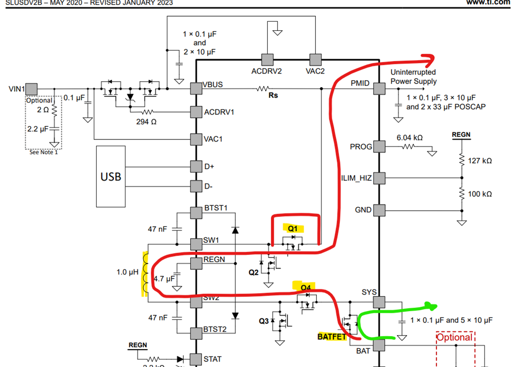
When one of the adapters is plugged in to VBUS, we will get an output on SYS anyways, as well as charge our battery if needed, and then when the adapter is removed it makes sense SYS would have no issues transitioning to the battery faster than PMID, since its separated only by the BATFET.

I am having trouble understanding why PMID exists really...it seems simpler and more efficient to just remove PMID all together and just use the SYS output as a UPS and regular system load...

Thanks,

Nicolas

  • Hi Nicolas,

    PMID is the input to the converter so the minimum recommended capacitance on PMID is required.  Resistor Rs shown in the block diagram between VBUS and PMID is needed to measure the input current or output current if the converter is used in reverse/OTG mode. Some applications are okay with the system load at SYS and following the battery down as it discharges when VBUS goes away.

    Some applications have a system load connected at PMID. When VBUS is applied, VBUS=PMID ignoring the IR drop across Rs and VBUS powers this system load.  When VBUS is removed, the system load still needs a regulated voltage, usually the same as at VBUS, so the IC can be configured for backup mode = fast turn on OTG/reverse mode.

    Regards,

    Jeff   

  • I won't be using OTG in my application, but I guess from what you're saying, is if certain applications need a regulated output voltage, then PMID can supply some specified voltage at PMID via OTG/reverse back-up mode? But for other applications where they have their own buck-boost they can tap off the battery directly via SYS?

    In my case, I am making an IoT node that will get power from a solar panel, with the option to use a USB adapter to charge the battery if you bring it inside or bring power outside at night or something. My idea is to have the power electronics get power from the solar panel when there's enough light, and then have it switch over seamlessly to getting power from the battery when there is not enough light to sustain the minimum system voltage... Would this still function the same as an uninterruptable power supply?

    Basically, when VBUS is removed, from either VAC1 or VAC2, will the SYS output transition cleanly to using the battery and not cause any brownouts downstream? I plan on using my own buck-boost converter with a wide input range, attached to the SYS output, so I don't mind tracking the battery voltage directly.

    Thanks,

    Nicolas

  • Hi Nicolas,

    Yes to first and second and third questions.

    Since using a solar panel with BQ25798 and if you will allow the battery to completely discharge, I suggest that you read https://www.ti.com/lit/pdf/sluab26.

    Regards,

    Jeff

  • Awesome! Wow, great write up as well! I appreciate the effort that went into researching this and coming up with a simple solution for preventing that issue, I didn't even think about that! 

    I'll let you know when I get around to finishing the schematic capture and PCB layout for final review before production. 

    Thank you for all your help and expertise! 

    Have a great weekend,

    Nicolas