A related question is a question created from another question. When the related question is created, it will be automatically linked to the original question.
If you have a related question, please click the "Ask a related question" button in the top right corner. The newly created question will be automatically linked to this question.
This is for a Automotive Application.We are using this as our primary buck which is turning up our microcontroller.The PGOOD is going in as a hard RESET to our micro, which makes it critical for our application.
VIN=Battery Voltage from vehicle-Range is from 8V to 16V
VOUT=5V Fixed(Using fixed variant from TI)
FSW=400KHz(want for better EMC performance as it is our main buck)
LOADs include microcontroller and other peripherals which in worst case source a current of around of 2.6A rms
I have a requirement to meet the sleep current requirement.
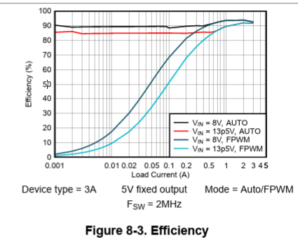
Can you please provide the efficiency curve for lower load currents of around 100uA to 200uA as the below snippet is only till 1mA.
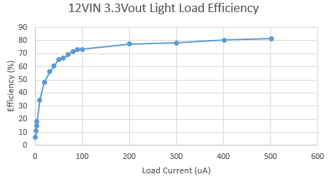
To meet the sleep current requirement as it has better efficiency at lower load currents I have changed the design to AUTO MODE by keeping the other circuit same