Other Parts Discussed in Thread: LM5185
Tool/software:
Dear TI team,
I used LM5185-Q1 designed a dual output flyback circuit, but work abnormally.
Would you please help check the protential issue?
Detail:
1. the design is referred TI calcuate doc, detail refer to the attachment.
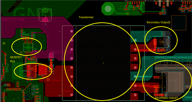
2. schematic is attached.
3. when we got the PCBA, we powered on, and found the transformer is squealing.
4.we found the primary voltage is uncontroller, and will reach around 60V, and ICs connected with the secondary outputs are damaged.
5.We guess maybe this is caused by the dummy load is too light and no zener diode protection for the outputs.
6. We removed the damaged parts, add 8.5k load (resistors) and TVS (we only have TVS in hand) for outuput, but still can not work.
7. When we increased the dummy load from 8.5k to 4k to 2k to 1k to 250ohm, the output is out of control.
2k Vout can output but is 235V;
1k Vout can output but is 205V;
250 Vout can output and is 174V;
8. It seems the output is out of control.
-----Would you please help check the protential causes except dummy loads or zener diode proteciton?
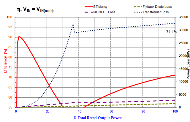
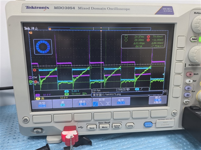
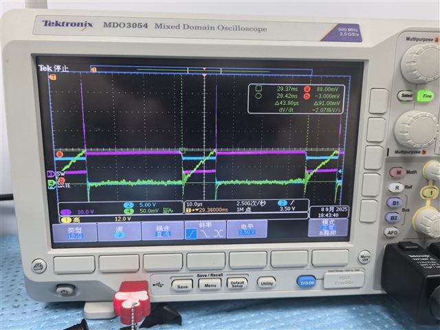
-----From the test waveform of VFB/gate/ Isense of primary, none of the modes are identical to the description in the datasheet, why? Not 20mV trigger FFM, not 350k DCM, not 100mV BCM!!!
-----Why output voltage loss control, how does this IC found the knee position? It seem the setting of RFB is not working.
-----For FFW mode, the MOSFET turn off is decided by the voltage on Rcs, if reached 20mV, turn off the MOSFET. but how to decide when to turn on the MOSFET and how to decide the Frequency? LM5185-DESIGN-CALC---2.xlsxLM5185 FLYBACK.pdf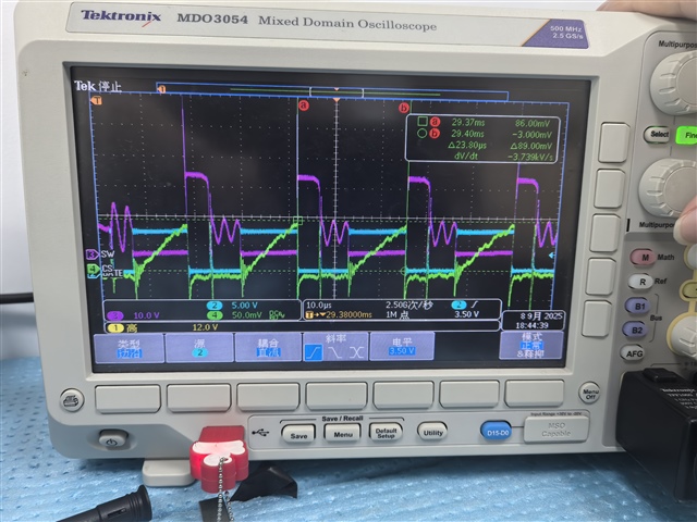

 we have add kinids of loads on output, but can not work.