This thread has been locked.

If you have a related question, please click the "Ask a related question" button in the top right corner. The newly created question will be automatically linked to this question.

UCC12041-Q1: EMI test issue

Part Number: UCC12041-Q1
Other Parts Discussed in Thread: UCC12040, LM25180, UCC12050EVM-022, UCC12051-Q1, PMP22845

Tool/software:

hi TI expert

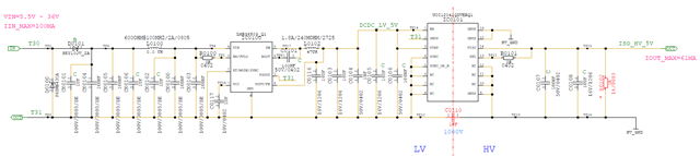
Here is Hella R&D, We used UCC12041-Q1 for isolated DCDC application

Schematic diagram as below:

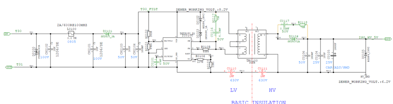
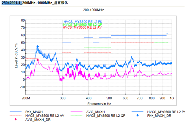
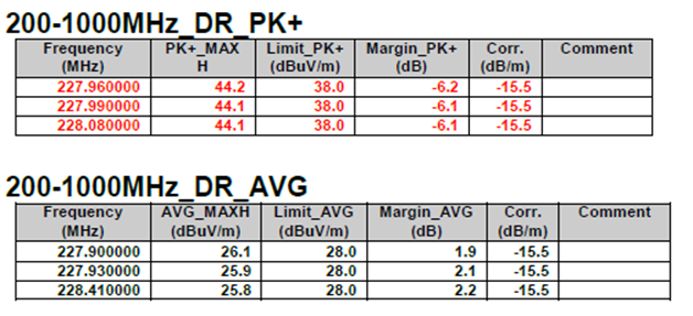
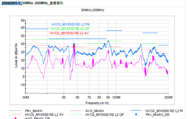
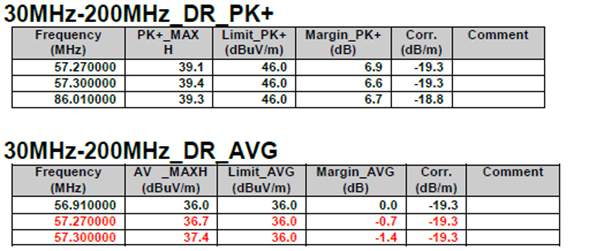
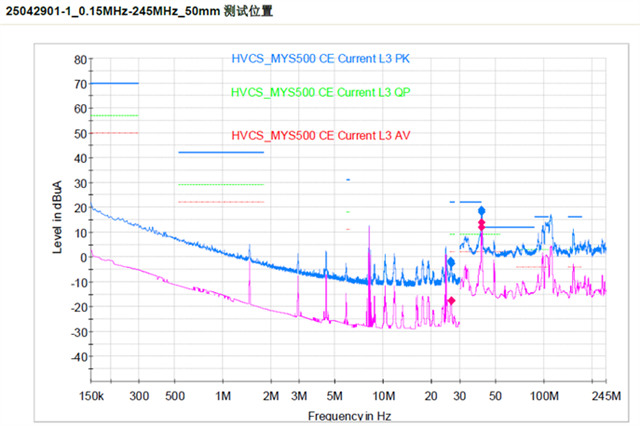
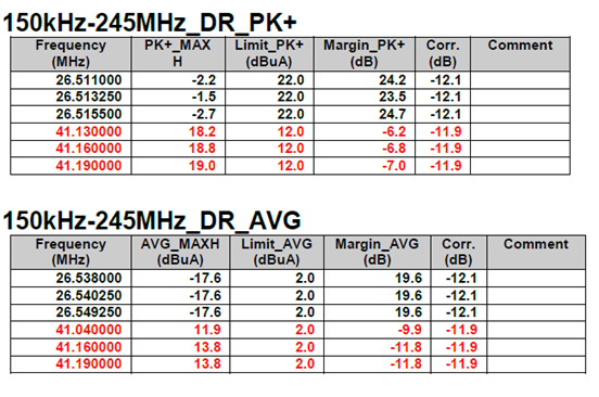
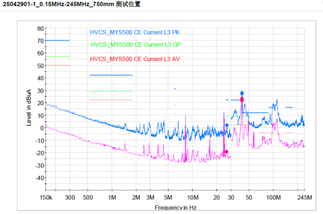
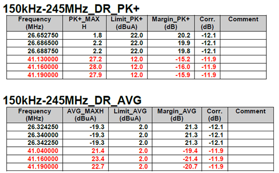
Our product failed in RE/CE test , the result as below

Can you support to fix this issue,?

pls. share your comments and countermeasures

Two more question:

1,does common choke inductor mandatory?

2,Why Y capacitor recommended 110pF? theoretically 110pF will pass more high frequency to input power line, which will cause CE test fail more easily

Test result as below

CE fail, 41MHz

RE fail, 57MHz, 227MHz

  • Hi Hella,

    You mentioned that you used UCC12040, however, your schematic shows LM25180 which is a PSR Flyback converter. Please, confirm the device and also share the correct schematic.

    Thank you

  • Sorry, correct schematic as below

    this schematic was reviewed TI BU before, that is why we released with confidence

    But RE/CE failed during DV test.

  • Hello,

    Manuel must be away from the office at this time. He or another expert will respond to your question by the next business day.

    Regards,

  • Hella,

    The UCC12041 will need some EMI filtering components in order to pass the CISPR32 standard. Two filters that will help pass CISPR32 are a stitch capacitor and ferrite beads.

    First making C110 a stitch capacitor will improve EMI significantly. To make this happen extend the copper planes on the inner layers of the PCB so that they overlap and create a capacitor. This technique is demonstrated in the design of UCC12050EVM-022:

    Second select and place the ferrite beads according to this applications note:

     6403.UCC12050 CISPR32 EMI RE CE.pdf

    One significant difference between your design and the example in the application note is the buck converter in between T30 and UCC12040. You may want to consider placing the ferrite beads in between the buck converter and T30 instead of in between the buck converter and UCC12040.

    If you also need to pass CISPR25 then PMP22845 will be a good reference. This is a design for UCC12051-Q1 but it will be a good guide for this part as well.

    Regards,

    Carter

  • hi Carter

    Thanks for your comments, but still 3 questions:

    1,extend the copper planes on the inner layers, which shorten the creepage distance , will it decrease high voltage withstand? 

    2,in the RE/CE application notes, is the bead FB2 mandatory?

    3,the EMI design in PMP22845 , common choke and Alu capacitor required, which is not proper for our real design, is the components mandatory?

    especially the Alu capacitor is too big that there is no space on our PCB to place

  • Hi Kai,

    1,extend the copper planes on the inner layers, which shorten the creepage distance , will it decrease high voltage withstand? 

    The guidelines for how much space is needed between the primary and secondary sides on inner layers is far smaller than on the top and bottom layers because they are not exposed to the air. It will not decrease the voltage rating of the design.

    For questions 2 and 3 it depends on what standard you need to pass. In the application note I linked above about the ferrite beads it states "When PCB is properly designed, no ferrite beads will be required to pass CISPR32, Class B". The CMC and the Alu capacitor are also not required to pass CISPR32, but they may be required to pass CISPR25. I would compare the standard you are looking to pass with the standards referenced in the application note linked above and the users guide of PMP22845 to determine what filtering components you will need in order to pass.


    Regards,

    Carter

  • hi Carter

    Our design is required to pass CISPR25 class 3, but CMC and Alu capacitor is too big to place, can you recommend other countermeasures?

  • Hi Kai, please see my feedback below regarding CISPR25 Class 5 for UCC120x0-Q1

    -You can use this CMC 744232102 from WU which has a lower footprint and provide similar insertion loss than previous CMC

    -C14 and R11 is a damping network used to damp the 50uH inductance coming from the LISN. If you are using a pre-regulator to step down the voltage from 12V to 5V such as an LDO or buck converter, you do not need to use C14 and R11. 

    -Finally, as Carter mentioned, it is recommended using a stitch cap to reduce CE and RE emissions. Is the system allows, you can use a Y-cap as an alternative. A Y-cap is a capacitor connected between the isolated ground planes to provide a return path to the CM (common mode) currents. Depending on your isolation voltage requirements, you might need one or two Y-caps. Here is a part number recommendation CC45SL3DD221JYNNA.

    Thank you