


Tool/software:
Hi,
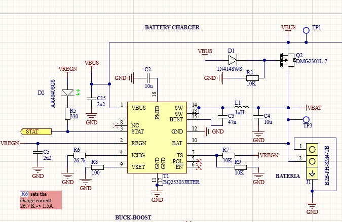
I have a design using your IC BQ25303J, and as suggested from one of your employees from technical support ( BQ25303J: Typical Application circuit from datasheet) I did not implement the schematic mentioned in "10.2.2 Typical Application with External Power Path" but an alternative suggested by him: "connect VSYS (i.e. system output) directly to VBUS pin rather than at PMID pin"
I have produced prototypes of this PCB and I have found it works fine with a "dummy" charger (5V fix), but it does not always work with smart chargers.
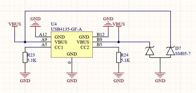
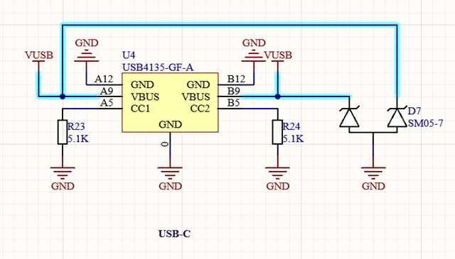
I have properly placed the 5.1k resistors on the USB side.
I have found out that it seems the smart charger does not like to see any voltage on the VBUS when it is connected.
To solve that I have found though that two possible implementations work:
1) Going back to the original schamatic that was detailed in the datasheet. I am worried though because in the previous ticket, the technician suggested "The BQ25303J will sometimes have issue properly detecting an input unplug when there is a large enough load connected at PMID. Due to this we recommend no system load be connected to PMID pin. "
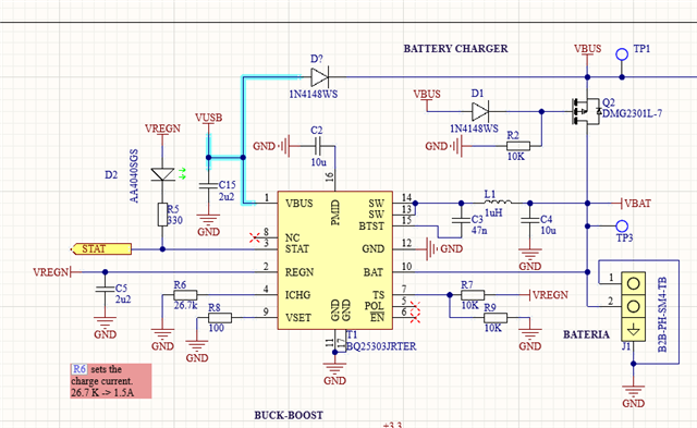
2) Isolating VUSB from VBUS. VUSB goes to pin 1 from BQ25303J
What would you recommend me?
Thank you.
