Tool/software:
Hi,
I am having trouble with my TPS48161 application. The application is designed for 24V nominal (18-32V) and 30A max.
My application needs to start capacitive loads so I use a soft start mosfet with some series resistors connected to G and controlled by INP_G as per the datasheet. The main mosfets are connected to GATE and controlled by INP.
When I test with no load, the INP and INP_G inputs drive the mosfet gates connected to GATE and G respectively and the output voltage comes up without a problem.
When I test with a 100 Ohm load, driving INP_G high causes the FLT pin to assert (low). The soft start mosfet stays off. When INP_G is driven back down, FLT de-asserts (high). Then the main mosfet connected to GATE switches on and brings up the output voltage.
When I test with a 10uF capacitive load, driving INP_G high causes the FLT pin to assert (low). The soft start mosfet stays off. When INP_G is driven back down, FLT de-asserts (high). Then the main mosfet connected to GATE appears to switch on but appears to have a problem with the inrush current and very quickly turns off. The output voltage rises very quickly to a few volts then discharges away again.
Why would FLT assert when INP_G is driven high with such small loads?

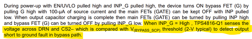
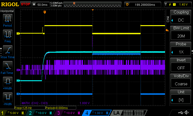
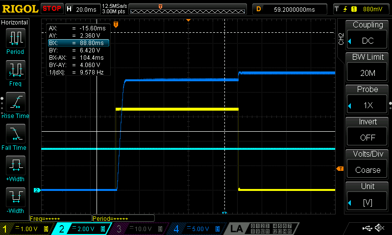
Input 1: INP_G, Input 2: INP, Input 3: G, Input 4: GATE
No load starting works fine. This same sequence of INP_G high for 200ms then INP high is repeated for the scope captures below.
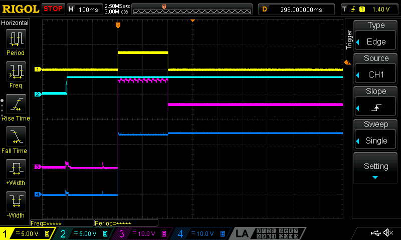
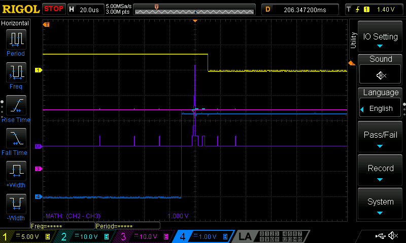
Input 1: INP_G, Input 2: FLT, Input 3: G, Input 4: Output Voltage
No load starting works fine.
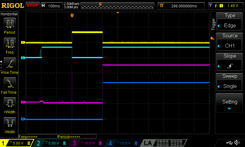
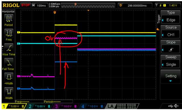
Input 1: INP_G, Input 2: FLT, Input 3: G, Input 4: Output Voltage
100 Ohm resistive load. Driving INP_G high causes FLT to assert (low). Soft start mosfet does not switch on.
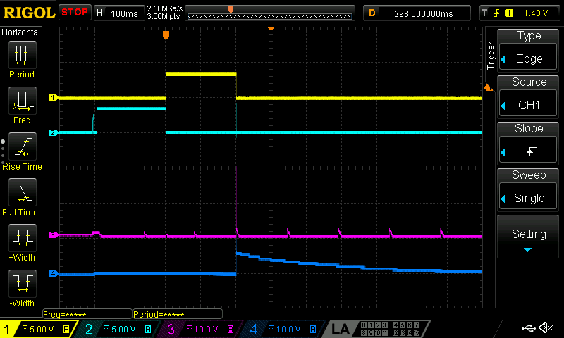
Input 1: INP_G, Input 2: FLT, Input 3: G, Input 4: Output Voltage
10uF capacitive load. Driving INP_G high causes FLT to assert (low). Soft start mosfet does not switch on. Main mosfet switches on but turns off very quickly causing output capacitor voltage to increase rapidly but then discharge again.