BQ25756E: No current but good status

Part Number: BQ25756E
Other Parts Discussed in Thread: TPS25751, BQ25756

Tool/software:

Hi there, 

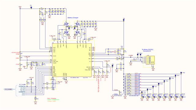
I have the TPS25751DREFR connected to the BQ25756E. 
The charge status status it is under fast charge and the STAT lines display a charging state but no current is flowing. All the status registers are clear with no faults. 
Charge enable is active and the power good signal is active. 

Would much appreciate any help or direction! 
Thank you


Below is my config:

{
"questionnaire": {
"device": "TPS25751",
"toolBuildVersion": "1.1.1",
"answers": [
null,
4,
4,
1,
1,
0,
3,
0,
1,
1,
1,
4,
0,
0,
1.536,
2,
2,
2,
0
],
"vendorId": "0000",
"productId": "0000",
"version": "1.0.0.2"
},
"configuration": {
"data": {
"selected_ace": [
{
"register": 6,
"data": [
0,
0,
0,
0,
0,
0,
0,
0
]
},
{
"register": 22,
"data": [
0,
0,
0,
0,
0,
0,
0,
0,
0,
0,
3
]
},
{
"register": 40,
"data": [
0,
0,
46,
1,
0,
0,
0,
0,
0,
0,
0,
0,
0,
0,
0,
0,
1
]
},
{
"register": 41,
"data": [
50,
80,
128,
0
]
},
{
"register": 50,
"data": [
0,
170,
42,
44,
145,
1,
32,
44,
209,
2,
0,
44,
177,
4,
0,
244,
65,
6,
0,
244,
177,
4,
224,
0,
0,
0,
0,
0,
0,
0,
0,
0,
0,
0,
0,
0,
0,
0,
0,
0,
0,
0,
0,
0,
0,
0,
0,
0,
0,
0,
0,
0,
0,
0,
0,
0,
0,
0,
0,
0,
0,
0,
0
]
},
{
"register": 51,
"data": [
2,
44,
145,
1,
16,
44,
209,
2,
0,
44,
177,
4,
0,
244,
65,
6,
0,
0,
0,
0,
0,
0,
0,
0,
0,
0,
0,
0,
0,
0,
0,
0,
0,
0,
0,
0,
0,
0,
0,
0,
0,
0,
0,
0,
0,
0,
0,
0,
0,
0,
0,
0,
0
]
},
{
"register": 55,
"data": [
118,
192,
18,
65,
180,
144,
33,
0,
0,
0,
0,
0,
0,
0,
0,
0,
0,
0,
0,
0,
0,
0,
0,
0
]
},
{
"register": 66,
"data": [
26,
0,
8,
0
]
},
{
"register": 92,
"data": [
1,
12,
0,
0,
0,
0,
0,
0,
4,
0,
0,
0,
5,
4,
0,
0,
0,
4,
0,
0,
0,
0,
0,
0,
0,
0,
0,
0,
0,
0,
0,
0,
0,
0,
0,
0,
0,
0,
0,
0,
0,
0,
0,
0,
0,
0,
0,
0,
0
]
},
{
"register": 112,
"data": [
3
]
},
{
"register": 119,
"data": [
0,
0,
0,
0,
0,
0,
0,
0,
0,
0,
0,
0,
0,
15,
0
]
},
{
"register": 120,
"data": [
0,
0,
0,
128
]
},
{
"register": 122,
"data": [
0,
0,
0,
0
]
},
{
"register": 123,
"data": [
0,
2,
255,
255,
0,
0,
0,
0,
0,
0,
0,
0,
0,
0,
0,
0
]
},
{
"register": 125,
"data": [
0,
0,
0,
0,
0,
0,
0,
0,
0,
0,
0,
0,
0,
0,
0,
0,
0,
0,
0,
0,
0,
0,
0,
0,
0,
0,
0,
0,
0,
0,
0,
0,
0,
0,
0,
0
]
},
{
"register": 126,
"data": [
0,
0,
0,
0,
0,
0,
0,
0,
0,
0,
0,
0,
0,
0
]
},
{
"register": 152,
"data": [
0,
0,
0,
0,
0,
0,
0,
0,
0,
0,
0
]
}
]
}
}
}
  • Hello Drew,

    Thanks for working with this. I have a few questions to help debug this.

    • Are you using the EVMs or a custom board?
      • If you are using a custom board, can you send me the schematic?

      • Have you made any adjustments to the EVM?

    • What's the input voltage and the battery voltage?

    • Can you read the status and flag registers of the BQ25756E?

    Best Regards,
    Ethan Galloway

  • Hi Ethan,

    This is a custom board.


    Input voltage can vary since this is connected to the TPS25751D. The TPS is configured to enable the CHARGE_EN when it starts up. 
    I realized that the status and faults are cleared after the first read so therefore there are some indications. 
    So, the DRV_SUP has faulted and the input under-voltage flag has faulted. 
    DRV_SUP measures at 4V and Vacuv is shorted to PPHV on the schematic. 

    Battery Voltage is at 3.64V currently.
    The config for the TPS is above. 

    Reg Description Value
    0x21 status 1 0x03
    0x22 status 2 0x80
    0x23 status 3 0x00
    0x24 fault status 0x00
    0x25 charger flag 1 0x69
    0x26 charger flag 2 0x80
    0x27 fault flag  0x82


    Thank you for the review. 

  • To add to the above:

    I attempted to turn the CHARGE_EN on after the PD negotiations and the input under-voltage flag was not tripped. My suspicion is that the BQ25756 is pulling too much power before PD negotiations are done and therefore pulling the power down to create an under voltage condition. 

    Could this be happening? If so, is there a better method for enabling the CHARGE_EN?
    This is unconfirmed though. 

    Thank you

  • Hello Drew,

    Thanks for working on this.

    There are a few things in the schematic that could be improved:

    • The BTST capacitors will need to be 100nF.
    • If the system isn't using ACUV/ACOV, you'll need to short ACUV to VAC and short ACOV to GND.
    • The system will need to have the capacitance balanced across the sense resistors. You can see this FAQ for more information.
    • Can you send me the inductor and FET datasheet or part numbers? I want to make sure that these parts will work with the BQ25756.
    • I recommend only connecting DRV_SUP to either PP5V or REGN. Shorting DRV_SUP to REGN may make initial testing easier.

    Best Regards,
    Ethan Galloway

  • Ethan,

    Thanks a ton for the help! 

    We currently have ACUV shorted to VAC and ACOV shorted to GND. 
    We changed the BTST caps to 100nF and shorted REGN to DRV_SUP with no change. 
    I am still getting the same results from the BQ25756E registers. 

    FETs: SQS482EN-T1_GE3
    InductorSRP1510CA-100M

    Please let me know if these parts don't seem adequate! 
    Thank you!


  • Hello Drew,

    Thanks, those inductors and FETs should work for your system.

    I have a few test suggestions / questions to help debug this:

    • What's the input voltage for your system?

    • Can you measure the voltage on REGN?

    • Are you seeing SW1 and SW2 switch on the oscilloscope?

    • What will be the maximum input voltage and input current of your system?

    Also, it's normal to see the DRV_SUP flag and VAC_UV set to 1 on startup.

    Best Regards,
    Ethan Galloway

  • Ethan,

    Thank you for being so responsive!

    If by system, you mean our "system" net, that is connected to 8 lithium ion batteries connected. Nominally 3.7V.
    If you mean the PPHV, then we are shooting for 20V, but simply trying to get it to work currently. 

    REGN is measuring at about 5.3V. We have tried swapping DRV_SUP to PP5V and REGN with similar results. 

    SW1 and SW2 are switching but only at 20kHz. We have verified R14 to be at 66.5k Ohms. 

    The system was designed for 20V and 5A from the USB PD. 

    Thanks for the tip about the flags, been chasing those for the last two days. 

    Anything else we can try?

    Thank you!


  • Hello Drew,

    Thanks for being patient with the delay in this response. My team has been running a seminar this week.

    The USB-PD team got back to me and said the schematic was good.

    I've got a few more questions:

    • What input voltage are you using?

    • Can you measure the voltage on the VAC pin?

    • If you charge your battery to 4V, does source mode work? You can also use a normal voltage power supply to test source mode.

    Best Regards,
    Ethan Galloway

  • Hi Ethan, 

    Thank you for the reply. 
    We made a little bit of progress here. I wired in a power supply to VAC in an attempt to isolate the issue and I was able to charge the battery with 15V input at 15A to the battery.  

    Now, when I try to use the TPS to deliver more power from PD, I get some faults. Below is VAC. This is negotiating from 5V to 9V and then seems to be resetting. The CE pin is shorted to GND. 


    This is a different USB PD plug:

    After this happens, I get these flags:
    Charger Flag 1 = 0x41
    Charger Flag 2 = 0x80
    Fault Flag = 0x02

    And then:
    Charger Status 2 = 0x80

    Hopefully this helps. 
    Thank you!


  • Hi Drew, 

    Supporting this from the USB-PD side, what source (charger) device are you using to test charging your system with and what is its power capabilities?

    Thanks and Regards,

    Raymond Lin