UCC28951: PSFB CURRENT DOUBLER EQUIVALENT OUTPUT ARCHITECTURE

Part Number: UCC28951


Tool/software:

We are evaluating the design of a PSFB with 400Vin; 28Vout ; 200A.


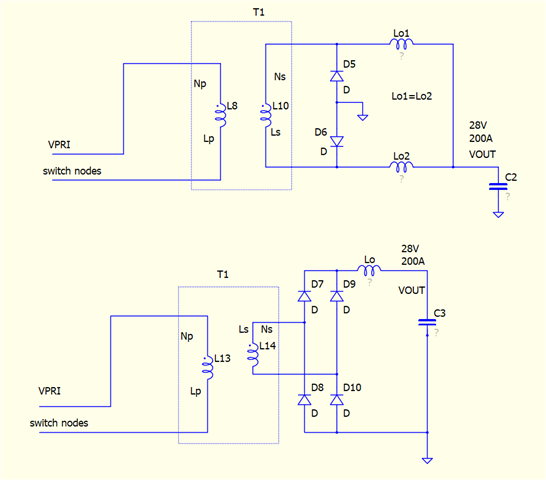
Our current ideas is to use the following output stage that use two transformers with series connected primary windings and parallel current doubler outputs. 


In literature the basic design formulas of a PSFB use output architectures like single stage current double or full bridge recitiffer. We need help on identify the relationship between our architecture and one of the following two architectures in order to use the design formulas from the UCC datasheet or literature formulas. We must identify how Np1, Ns1, etc.. parameters modify from our architecture to/from one of the following basic architectures.


Thanks

  • Hi Nicola,

     Since the primary voltage is split, assume half of the VIN to use the formulations that were used for current doubler.

    Regards
    Hemanth

  • Hi Hemanth. Thanks for your feedback.

    Yes, since the primary winding is splitted the VIN should be considered as half.

    But:

    -Turns ratio: How do you change it? (formula 25 in datasheet)

    -The primary inductance is Lp1+Lp2, so how should I treat primary inductance in calculations if i consider VIN/2? (formula 28 in datasheet)

    -The two secondaries are in parallel, so what about the inductors (Lo1 to Lo4) ripple current?  (formula 27 in datasheet)

  • Hi Nicola,

     I will get back to you by today.


    Regards
    Hemanth

  • Hi Niclola,

    Here is my response.

    Please consider the design as if you are designing one converter with VIN/2 as input voltage, VOUT as the output voltage. Once one design is ready, you can use the same for the 2nd instance (series primary, parallel secondary though).

     Formula 25 - since VINMIN and VIN are already part of the equation; the turns ratio would already be half (half the number of primary turns).

    Formula 28 - If you consider primary inductance as Lp1 (=Lp2) and consider half of VIN in place of VIN to design one of the two sections of the converter.

    Formula 27 - Ripple current is a design choice. Since the secondaries are connected in parallel, the ripple current ratio doesn't change from single converter design. Ripple current gets doubled, also the average current also gets doubled with 2 parallel secondaries and the ripple ratio remains same.

    Regards
    Hemanth

  • Hi Hemanth, thanks for the info. Very useful.

    If i understand correctly, in Formula 28, If i consider VIN/2 in place of VIN i obtain Lmag=Lpri; is it correct?

    For what concern the computation of output inductor (Formula 61), once i define the desidered ripple current, how the Lout should be splitted between Lo1 to Lo4 in my architecture?

    Last question was related to the duty-cycle.

    Formulas 25 and 26 use Dmax and Dtyp. For example Dmax is considered 70%. According to SLUP414 Deff for a current doubler rectifier is 50%.

    So what is the link between Dmax and Deff?

    Also, still in SLUP414 the control logic waveform is as follows:

    So, why Dmax is greater than 50% in UCC datasheet? Is it allowed to have a duty gretaer than 50%.

    Can you clarify the Duty-cycle definitions?

    Thanks again

    Best Regards

  • Hi  Nicloa,

    1. Yes, Lmag = Lpri >= calculated value in (28).

    2. Ripple current impacts the life time calculations of capacitor, ripple voltage on output, core losses in inductor and inductance, inductor sizing, efficiency curve optimization etc. So, it is design choice of the design.

    DTYP would have already considered the half the VIN and turns ratio. Please note the switching frequency for the secondary inductance calculation in current doubler circuit is equal to the primary switching frequency (unlike in bridge rectifier, the ripple frequency is 2x the primary switching frequency). 

    So, considering the above, the formula (61) should give you the inductance that you need for L01 through L04.

    3. Since the current doubler inductor gets energized during let's say when there is positive voltage across primary, the freewheeling period includes both the zero voltage period and also negative voltage period. And hence, the maximum duty is lower than 0.5 automatically. The 0.7 max duty to be considered as 0.35 (or up to 0.4) for current doubler.

    4. The primary of the PSFB will have both positive and negative voltage across its primary, maximum half the period each (barring the dead times). If both the on periods (positive and negative voltage) are added and divided over the full period - yes the max duty can go beyond 0.5.

    D = (Ton1 + Ton2) / Tsw

    In other words, to define the duty for each half period -

    D = (Ton1)/(Tsw/2)

    Regards
    Hemanth