TPS6521905: Can't connect to USB2ANY

Part Number: TPS6521905
Other Parts Discussed in Thread: USB2ANY, TPS65219EVM-SKT, TPS65219, , MSP430F5529

Hi, 

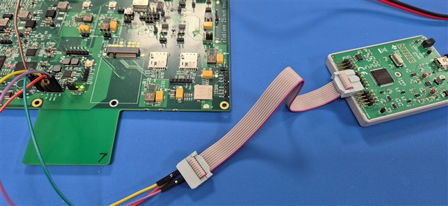
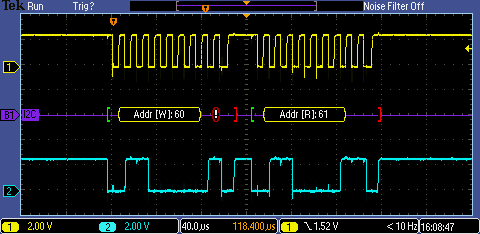
Back in May I designed in the TPS6521905 to my board. I spent some time in getting the TPS65219EVM-SKT to work with the GUI and getting it to program some devices. These have now been built into a handful of prototype boards and I need to access these devices. Currently they are producing the correct output voltages on each of 5 outputs I setup when the outputs are disconnected from the rest of the circuit, but once connected, the TPS6521905 refuses to turn on. To investigate this I have obtained a USB3ANY adaptor, but the TPS65219_GUI does not recognise it when plugged in. I have checked the operation of the GUI by connecting the EVM with fresh devices and successfully programming them, however, when I unplug the EVM and plug in the USB2ANY adaptor, the GUI attempts to attached to it, but returns with a "Hardware not Connected. Failed to connect. Reading finished." error message.

How should the USB2ANY be conneted to the GUI, please, if this method is correct, what am I doing wrong?

thanks for any help...

  • Hi David, 

    Just to make sure I'm understanding correctly, are you saying the connection with the TPS65219EVM-SKT board with the USB2ANY and GUI is failing?

    Or are you attempting to connect the GUI with USB2ANY on your custom board, and this is failing?

    In either case, are you able to measure the SDA and SCL voltages and make sure this is being properly pulled up to 3.3V? 

    If the pull-up source is powered by the pmic output, then I2C communication will not be available if the PMIC is not turning on correctly as you have said. 
    I would recommend using an external 3V3 pullup source here.

    Best Regards, 

    Sarah

  • Hi Sarah,

    Many thanks for your reply. I am attempting to connect the GUI to my custom board with the USB2ANY module. I have confirmed this afternoon that the possible reason for not having comms (there is no I2C comms) is that the output switch of the USB2ANY (U5 on the USB2ANY schematic) is not turning on.  This is controlled by the MSP430F55291PNR, isn't it? If so how does the GUI tell the USB2ANY to turn on its 3v3 output, and/or select its 5v output? I can't see anything in the available functions of the GUI that has this control over the USB2ANY module, although this may not be the cause of the lack of I2C comms.

    I have a separate 3v3 pullup source on the board.

    kind regards, David.

  • Hi David, 

    Thanks for the info here. 

    The GUI actually isn't interacting with the 3.3V pin of the USB2ANY at all, the SDA and SCL should be pulled up by your external 3V3 pullup source, so the USB2ANY's 3.3VEXT output is unused/not needed.

    As seen from our EVM schematics, pin 5 of the USB2Any adapter isn't connected:

    Would you mind showing how your board has the USB2ANY connections set up?

    Best Regards, 
    Sarah

  • Hi Sarah,

    Many thanks for your reply.

    Just to be accurate, I am using the USB2ANY module to connect to the TPS6521905 on my board, not the EVM, and the interface schematic for this is....

    This circuit does look like the MSP430F5529 has some control over the I2C interface, and is able to supply 3.3v output, but if the I2C lines still communicate whether or not this interface is setup, then that should be fine.

    So my circuit looks like this...

    and at the moment I can see the SCL and SDA lines are high at 3.3v, but there is no activity on them when I attempt to attached the USB2ANY module to my desktop running the 6521905_GUI. To my mind, the fact the GUI attempts to link to the USB2ANY but fails suggests there is a problem with the desktop talking to the MSP430F5529 on USB2ANY module rather than a problem with the I2C link to the PMIC.

    best regards, David.

  • Hi David, 

    Thanks for your response, 

    It looks like J44 in your schematic is the output to connect to the USB2ANY module.

    Are you just connecting these individually with female-female wires to the pinout of the USB2ANY module?
    J44 and J45 don't appear to be formatted as a 10 pin header for the ribbon cable. 
    Are you able to show a picture of how the module is physically being connected to your board, just so I understand?
    I'm concerned if the pin-outs aren't matching correctly. 

    To further ensure this isn't a GUI problem, 

    Can you also try running the USB2ANY explorer, check that your USB2ANY module is running the latest firmware,
    attempt to pull up the 3.3V ON and see if I2C is acknowledged?

    Best Regards, 
    Sarah

  • Hi Sarah,

    Yes, indeed, J44 is the connector for the USB2ANY module and I use female-female leads for that.

    I will send you a picture tomorrow when I am back in the office and I will also check the firmware with explorer.

    best regards, David.

  • Hi Sarah,

    Many thanks for the USB2ANY explorer suggestion, updating the firmware now allows the TPS65219_GUI to see the USB2ANY. However, the GUI now fails on being unable to talk to the TPS65219 device itself with error message "Connected to USB2ANY Controller, but failed to connect to TPS65219x on I2C @0x30"

    0x030 is the correct I2C address for my device.

    Here a photo of my setup...

    You may just be able to read that the SCL wire is connected to pin 2 of the USB2ANY module via the red wire, SDA to pin 1 via the yellow wire and GND to pin 5 via the purple wire. There is 3.3v on the board pulling up the I2C lines via 4.7K resistors. I cannot observe any activity on the I2C nets on my scope.

    best regards, David.

  • Hi David, 

    Thanks for the update, it looks like those pin connections are fine, 
    When you say no activity on the I2C lines, are these just constantly high?

    If you just use the USB2ANY I2C tab and attempt to read or write, does this show any activity on the SDA or SCL lines?

    The "failed to connect to TPS65219x on I2C @0x30" error message doesn't necessarily mean an address issue, this could also indicate a hardware connection issue, that it is not connected to the PMIC correctly, and not able to detect it properly. 

    Double check all your connections, and make sure there aren't any faulty wires or cables. 

    Best Regards,
    Sarah

  • Hi Sarah,

    Many thanks for your suggestion.

    I have now tried this approach to testing the I2C lines, and I have found that the USB2ANY module does issue read and write messages to the TPS65219, but there is no response from the chip. This is curious because I assume that so long as there is a 5v supply to the chip, and the I2C lines are pulled high, then the I2C part of the TPS65219 should always respond on the I2C lines. I am sure I have set the right address - 0x30 - and it is running at 100KHz. Having set the I2C address and requested a write to that address, the USB2ANY module is not acknowledged(NAK).

    Any further suggestions, please?

    kind regards, David.

  • Hi David, 

    This is interesting, the device should be responding as long as the I2C lines, VSYS, and EN are supplied, and everything is grounded correctly.  
    Just curious, how many vias are on the thermal pad of the PMIC? We typically recommend at least nine vias here.

    Are you able to hook up a logic analyzer / scope to the I2C lines and share images of exactly what you are seeing on the lines, just so I can understand better?

    Best Regards, 
    Sarah

  • Hi Sarah,

    I definitely have 9 vias on the thermal pad.

    Here is an attempted write...

    Here is an attempted read...

    numbers that I enter into the internal address box or write data box do not make any difference to what is seen on the I2C lines from these 2 images.

    kind regards, David.

  • Hi David, 

    Thanks for the scope shots, I see this is receiving the NAK error even though lines are active. .

    If you measure any of the other PMIC outputs, is this measuring as expected? 
    I am not sure of what test points you have available on your board, but are you able to check VDD1P8 is regulating correctly?

    I can only think of perhaps the PMIC was damaged and is not turning on properly, causing the NAK. 

    Best Regards, 

    Sarah

  • Hi Sarah,

    Thanks for your reply. 

    Yes, all 5 of my programmed outputs are at the correct voltage. 

    I have replaced the PMIC once with an unprogrammed device to see if that would communicate on the I2C bus, but again, no response. I will replace that one again with a fully programmed device once more in a few days and let you know the result.

    Many thanks, David.

  • Hi Sarah,

    I have made the progress I needed to. I can now read the registers in the TPS6521905 device on my board using the USB2ANY box! I believe it was due to something prosaic like rebooting my PC or changing the USB cable.

    At last I have got to the point where I can begin to work out why the chip is not working. With all the output lines disconnected to the main processor circuit, the PMIC produces the correct voltages, but when I insert the zero ohm resistors to connect the PMIC to the rest of the board, I get nothing out. I can see from the registers that there is a fault logged for buck regs 1 and 2, but I do not see any reason for this error to occur. I guess this is a different issue to log and not on this thread....

  • Hi David,

    Sarah is currently out of office. We can address your new concerns in a new thread, if you would be so kind to create another thread documenting what you have discovered I can take over and respond accordingly. 

    It is easier for tracking purposes from our side to create a new thread, thank you!

    Regards,

    Brandon