This thread has been locked.

If you have a related question, please click the "Ask a related question" button in the top right corner. The newly created question will be automatically linked to this question.

BQ34Z100-R2: Strange behaviour and code example for MSPM0

Part Number: BQ34Z100-R2
Other Parts Discussed in Thread: MSPM0G3507, BQ76952, BQSTUDIO, USB2ANY, EV2400

Hello

We are developing a BMS that has the BQ34Z100PWR-R2 fuel gauge. We are experiencing incorrect voltage measurement and we are looking for advice on how to fix this.

We have a 13s2p battery pack. I am attaching the Altium design files and firmware files to this post.

  1. We are able to communicate with the fuel gauge using a MSPM0G3507 MCU. we are able to read the voltage the fuel gauge senses. It reads 714 mV instead of expected 842 mV ( battery pack voltage is 50 V resistor dividers are 953k top and 16k bot).
    We have measured the voltage at the BAT pin and we see the voltage transitioning between the correct value of 842mV and 714mV. This repeats with a frequency of 1Hz. It seems that the fuel gauge samples the voltage which causes it to drop and then read the incorrect value.
    Is this expected? What are we doing wrong? How can we fix this?
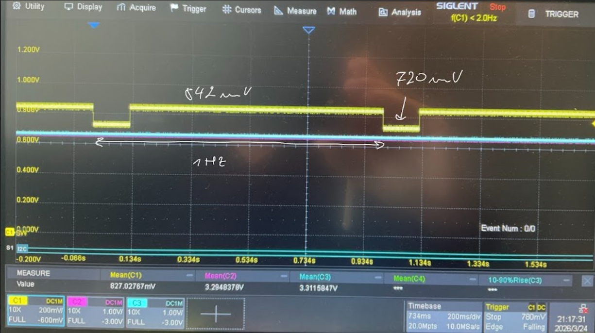
    image.png

  2. I would greatly appreciate any code examples for this fuel gauge using MSPM0 MCUs since we had great trouble coming so far. The code examples for BQ76952 were great and we had no issues using them. 
    Are there any code examples for this fuel gauge?

Please let me know what more information you need from my side so you can analyze the issue sucessfully.

Thank you all and best regards,

Samo Smodiš

260324 TI e2e ticket.zip 

260205 BMS v1 - Altium project.zip 

  • Hello,

    This question has been assigned within the team and will be reviewed and followed up with another application engineer when possible. In the meantime please attach any associated .log/.gg files associated with the projects

    Thank you,
    Alan 

  • #1: yes, the gauge samples this once a second but the voltage ADC input is very high impedance (several MOhms) so this should not affect the measurement. I can't open the Altium project. Please post a screenshot of your voltage divider and buffer circuit.

    #2: We do not have MSPM0 MCU example code for this gauge. It uses standard SBS commands to get the gauging results (basically just reading results using simple I2C commands). If you want to program the configuration, then you'll have to implement a simple FS parser (FS is a text file format that has the I2C instructions required to configure the gauge). See e2e.ti.com/.../faq-bqstudio-what-is-the-ti-bms-flashstream-file-format

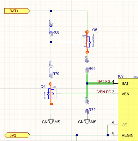
  • #1 Here is a screenshot of the schematic. I am also attaching a PDF of the whole schematic if you can open that.

    The mosfets Q5 and Q6 are bypassed as marked with red. The osciloscope measurement in the previous post is made on pin 4 BAT.

    Is it possible that the internal voltage divider of the fuel gauge is being connected to the BAT pin when the fuel gauge samples? This would explain the drop in voltage on the BAT pin as the resistance of the internal voltage divided is in parallel to the bottom resistor R72 which lowers the equivalent resistance and hence lowers the measured voltage. 

    I assume this might be the issue which means that we have not correctly configured the fuel gauge for 13s cell, but it still thinks that it measures only 1s cell. This would also explain why it does not scale the measured voltage when reading with Voltage() command?

    #2 I have a feeling that the way of using the MCU to configure the fuel gauge is not the best and is quite complex and error prone. We did this because we did not have an EV2400 adapter at hand to connect the fuel gauge to the BQStudio. We are thinking of ordering the EV2400 to use the BQStudio. What is the simplest way to configure the fuel gauge? At the moment we have USB2ANY and Aardvark I2C adapter at hand. Can we use any of those to configure the fuel gauge with the BQStudio right away?

    Thank you and best regards,

    260205 BMS v1 - SCH.pdf

  • You will see a change in voltage on BAT whenever the gauge pulses VEN. The idea is for R68/R70 to only be "on" when the gauge needs to take a measurement (so that there isn't unnecessary discharge through this resistor divider when it's not in use). The voltage of the resistor divider is buffered with Q5 and divided again with R69 and R72. You need to choose these resistors so that the voltage, when VEN is on, is within the required range for BAT (because that's when the gauge measures voltage).

    The best way for developing a configuration is using bqStudio and an EVM. Once this works, you export a Golden Image, which can be programmed with the MCU.

  • I have the issue that VEN is never pulsed  and hence no voltage is present on BAT for measurement. Thats why I bypassed Q6 and Q5 like i marked in the schematic snippet above. Q6 and Q5 are now constantly on and play no role. Despite this I have voltage pulses on the BAT pin. Those pulses are not between 0V and 842 mV like I expected but are between 720 mV and 842 mV.
    Do you know what causes this?

    I will order the EV2400 and configure the fuel gauge with BQStudio. Can the BQStudio be used then to directly configure the fuel gauge or must I export the Golden image and configure using a MCU?

  • The gauge will pulse VEN once a second. This is hard-coded into the FW.

    bqStudio can directly configure the gauge. You do not need an MCU.