This thread has been locked.

If you have a related question, please click the "Ask a related question" button in the top right corner. The newly created question will be automatically linked to this question.

TUSB1064: S parameter model for TUSB1064

Part Number: TUSB1064
Other Parts Discussed in Thread: , TUSB1044A, TUSB1044

Hi Team,

We are evaluating TUSB1064 and try to use S parameter for simulation, downloading IBIS-AMI model and there are some questions regarding TUSB1064, please help to share your insights, thanks.

  1. In USB3.0 ibis model, TUSB1064_TXTERM.S4P has no S parameter curve, how to get a normal S parameter curve?

2. TUSB1064_RXTERM.S4P has normal S parameter curve, but it seems has insertion loss difference compare with the theoretical curve(Red curve), normally it should be 0dB in low frequency and become larger in high frequency range.

3. Are there any other S parameter which can be used for customer's evaluation? 

BRs,

Frank Cai

  • Hi Frank,

    Yes there s4p files seem  to be incorrect. 

    Can the customer try using these files? These are files for TUSB1064-Q1. The primary difference between the TUSB1064 and TUSB1064-Q1 is the packaging. This will slightly impact the s4p performance, but this deviation is no more than that of lot to lot variation of TUSB1064. These files should provide a sufficient approximation for the TUSB1064.

    This is for the USB path at EQ setting 0. 

    https://e2e.ti.com/cfs-file/__key/communityserver-discussions-components-files/196/1_5F00_1_5F00_RX1_2D00_to_2D00_SSRX_5F00_FF_5F00_3.3_5F00_25.0_5F00_0_5F00_1_5F00_0_5F00_0_5F00_deemb.s4p

    https://e2e.ti.com/cfs-file/__key/communityserver-discussions-components-files/196/1_5F00_1_5F00_SSTX_2D00_to_2D00_TX1_5F00_FF_5F00_3.3_5F00_25.0_5F00_0_5F00_1_5F00_0_5F00_0_5F00_deemb.s4p

  • Hi Vishesh,

    Already downloaded the model, there are some few questions may need your insights:

    1. the import is 1-3 and 2-4, right?

    2. We saw the S13 insertion loss is still abnormal, can you please check the following?

    3.The S21 and S12 is not the same, accordingly they should be same, right?

    BRs,

    Frank

  • Hi Frank,

    Can you test 1-2 and 3-4? We have two validation engineers and they both use difference s4p schema. 

    Yes s12 and s21 should be similar. here one loos like insertion loss and the other looks like FEXT.

  • Hi Frank,

    I have confirmed with the validation engineering team.

    1) The TUSB1044A SSTX and SSRX are unidirectional buses, this is why we see that the S12 forward pass is ok, but the S21 reverse pass looks to be similar to crosstalk performance. 

    2) This is true across all TI's USB redrivers. 

  • Hi Vishesh,

    Customer is testing 1-2 and 3-4 channel, will let you know if there are any questions.

    Btw, could you please help to confirm HPDIN can be connected from AP processor HPDIN and then these HPDIN signal can be translate to PD controller by I2C? And also, do we have our PD controller pair with USB1044 application? Thanks.

    BRs,

    Frank Cai

  • Hi Frank,

    The TUSB1064 does not generate a HPDIN signal. This will come from the AP processor. This signal can be connected to the HPDIN pin of the part, and this HPDIN signal can be used to enable/ disable DisplayPort Alt. mode functionality. 

    these HPDIN signal can be translate to PD controller by I2C?

    This is a question for the PD controller team. The TUSB1064 can work with a virtual HPD over I2C, but I dont have expertise with PD controller. 

    We have existing documentation for the following PD controllers working with the TUSB1044, the use case should be similar:

  • I would suggest to use a different thread for HPDIN signal, if there is a TI PD controller being used in this design.

  • Hi Vishesh,

    Thanks for detailed introduction.

    Let's get back to TUSB1064, We are using a cable for simulation and found that the eye diagram result is poor. The TUSB1064 has equalization, and we would like to adjust the eye diagram result through this equalization. However, we do not have this simulation file at present. Could you please send us the simulation file for adjusting the equalization?

    BRS,

    Frank

  • Hi Frank,

    The IBIS AMI file can be found here: https://www.ti.com/product/TUSB1064#design-tools-simulation

    This IBIS AMI file works with the Keysight ADS software. I will be using the 2023 Update 1 release version.

    Here are the stesp:

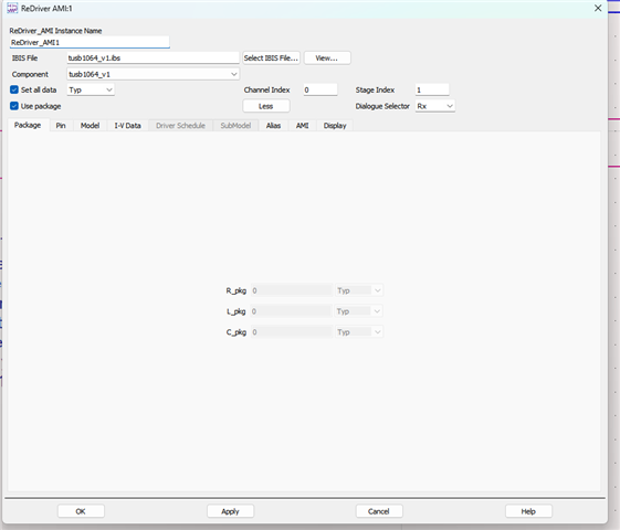
    1) Open IBIS AMI file. This can be done by creating your own schematic or using the pre-built archived file (.7zads). I will be using the pre-built schematic.

    2) Double click on the ReDriver_AMI block.

    3) Select the AMI tab and click on EQ RX AMI parameter:

    4) The default EQ setting will be 0. to manually adjust the EQ deselect the Use 'Set all data' setting, and adjust the Selected RX AMI parameter to user specified.

    5) Manually adjust the EQ and click apply.

  • Hi Franck,

    This is the only training resource we have.

    Simulation Training_SIwave.pptx

    You may want to look at the following training video series on youtube: www.youtube.com/playlist