This thread has been locked.

If you have a related question, please click the "Ask a related question" button in the top right corner. The newly created question will be automatically linked to this question.

NACK received over I2C communication in UCD9080

Other Parts Discussed in Thread: UCD9080, UCD9081

Sir / Ma'am,

I  have a  UCD9080 setup.I am trying to communicate with the IC(UCD9080) over the I2C line.First of all i am trying to configure the IC through 8 bit microcontroller.The communication happening over the I2C line is giving ACK for the Device Address and NACK for both Register address and Data.I am writing a 128 byte block of user data following with 512 byte block of configuration data.Please help me with the issue of NACK arising over the register address and data.How this should be troubleshooted and solved.Is there a software solution or a hardware solution for this ?

Regards,

Nipun

  • Can you confirm this is UCD9080 or UCD9081? While both are similar, there are a few bus access differences. I would recommend the following: 1) compare your host micro access algorithm with the "pseudo I2C transactions" algorithim shown in the UCD908x programming guide (http://www.ti.com/lit/an/slua441/slua441.pdf , appendix C.1 for UCD9080 or http://www.ti.com/lit/an/slva275b/slva275b.pdf , section 3.7 for UCD9081), or 2) compare the access methodology of the TI GUI using USB-GPIO EVM with your host micro methodology. Many times a bus sniffer such as Aardvark can be useful to track down the point of access failure.

    Both UCD9080 and UCD9081 have internal bus timeout mechanisms so if your host pauses too long between block writes (due to servicing of another interrupt of device on the bus) the UCD908x may discard the transaction.

  • We are using 0xc0 device address and writing 128 bytes (0x1080 - starting address) of user data and then 512 bytes of memory map parameters (0xe000 to 0xe1ff), is this device address is ok or it should be from 0x60 to 0x6f.

    Hex file is attached with 0xc0 address (complied in aduc831microcontroller (keil) environment) -

     This is 16 byte on one string, please check this is not meet as mention in appendix -A of http://www.ti.com/lit/an/slua441/slua441.pdf documents 

    :10084800546578617320496E737472756D656E7442
    :1008580073205543443930383020382D4368616E51
    :100868006E656C20506F77657220537570706C7967
    :100878002053657175656E63657220616E64204DE5
    :100888006F6E69746F7200000000000000000000C5
    :100898000000000000000000000000000000000050
    :1008A8000000000000000000FFFF00000000000042
    :1008B8000000000000000000FF0000000000C0026F
    :1008C8000000000F00020002FF0F005000000000AF
    :1008D8000000C020000000000000000000A8DCBAF2
    :1008E800101112131415161708090A0B0001020338
    :1008F800040506070000000005E005A032E033E02B
    :1009080033E035E035E000000000000000000000A2
    :10091800FF7FFF7FFF7FFF7FFF7FFF7FFF7FFF7FDF
    :100928007F000100020004000800100020004000C1
    :100938004D026C025501E8023402BA02BA02900173
    :100948008B02AA0293012603A40255035503C3028E
    :10095800A00FA00FA00FA00FA00FA00FA00FA00F17
    :1009680010001000100010001000100010001000FF
    :10097800FFC0FFC1FFC2FFC3FFC4FFC5FFC6FFC75B
    :10098800000000C000C000C004200820041802189D
    :10099800081810182018102000202020402080203F
    :1009A800000000049402F208100305C04000FF088C
    :1009B800050000000000000000000000000000002A
    :1009C800000000000000000000000000000000001F
    :1009D800000000000000000000000000000000000F
    :100FD20075AF21120FE31210241210121200268094
    :010FE200FE10
    
    
     This is 16 byte on one string, please check this is not meet as mention in appendix -A of http://www.ti.com/lit/an/slua441/slua441.pdf documents 
    
    
    :10084800546578617320496E737472756D656E7442
    :1008580073205543443930383020382D4368616E51
    :100868006E656C20506F77657220537570706C7967
    :100878002053657175656E63657220616E64204DE5
    :100888006F6E69746F7200000000000000000000C5
    :100898000000000000000000000000000000000050
    :1008A8000000000000000000FFFF00000000000042
    :1008B8000000000000000000FF0000000000C0026F
    :1008C8000000000F00020002FF0F005000000000AF
    :1008D8000000C020000000000000000000A8DCBAF2
    :1008E800101112131415161708090A0B0001020338
    :1008F800040506070000000005E005A032E033E02B
    :1009080033E035E035E000000000000000000000A2
    :10091800FF7FFF7FFF7FFF7FFF7FFF7FFF7FFF7FDF
    :100928007F000100020004000800100020004000C1
    :100938004D026C025501E8023402BA02BA02900173
    :100948008B02AA0293012603A40255035503C3028E
    :10095800A00FA00FA00FA00FA00FA00FA00FA00F17
    :1009680010001000100010001000100010001000FF
    :10097800FFC0FFC1FFC2FFC3FFC4FFC5FFC6FFC75B
    :10098800000000C000C000C004200820041802189D
    :10099800081810182018102000202020402080203F
    :1009A800000000049402F208100305C04000FF088C
    :1009B800050000000000000000000000000000002A
    :1009C800000000000000000000000000000000001F
    :1009D800000000000000000000000000000000000F
    :100FD20075AF21120FE31210241210121200268094
    :010FE200FE10
    
    
    please assist, what is setting mistake so that why it is not same as  appendix -A of http://www.ti.com/lit/an/slua441/slua441.pdf documents 
    
    
    thanks,
    sarita
  • The format of above .hex files does not look correct. After # of bytes at the beginning of a row, I expect to see the device address. For example in SLUA441 example hex file the first 32 bytes (0x20) are shown with device starting address highlighted:

    :20108000546578617320496E737472756D656E7473205543443930383020382D4368616EB3

    In your 16 byte hex file (0x10), we see: 10084800546578617320496E737472756D656E7442

    It appears that your addressing is not correct. How did you generate the hex file? FYI, the TI GUI will generate the .HEX file for you (File, Save Configuration and choose HEX as file type and extension).

  • Hello Sir,

    We tried out your GUI for generating the Hex file. We filled in all the desired values for the parameters (in reference to the excel file attached with this mail) which eventually resulted in generation of a Hex file which was in compliance with a sample Hex file displayed from your end.We loaded this Hex file which was successfully accomplished. Now we need to test whether it is operating correctly or not.How do we do that ? How to check whether the I2C Communication is happening properly or not ? The Hex file generated is displayed as below :

    :20108000202020202020202020202020202020202020202020202020202020202020202050
    :2010A000202020202020202020202020202020202020202020202020202020202020202030
    :2010C000202020202020202020202020202020202020202020202020202020202020202010
    :2010E0002020202020202020202020202020202020202020202020202020202020202020F0
    :20E00000000000000000000000000000000000000000000000000000000000000000000000
    :20E020000000000000000000000000000000000000000000000000000000000000000000E0
    :20E040000000000000000000FFFF7F00000000000000000000000000FF0000000000C00282
    :20E060000000000F00020002FF0F3750000000000000C020000000000000000000A8DCBADA
    :20E08000101112535455565700494A4B00000000000000060000000000000000000033E0AD
    :20E0A0003300350035E000000000000000000000FF7FFF7FFF7FFF7FFF7FFF7FFF7FFF7FF3
    :20E0C000000000000000000000000000000000000000000000000000000000000000000040
    :20E0E000000000000000000000000000000000000000000000000000000000000000000020
    :20E100007F00010002000400080010002000400000003601AB0074013502BA02BA0290016A
    :20E1200000045501CA009301A40255035503C302A00FA00FA00FA00FA00FA00FA00FA00F94
    :20E140001000100010001000100010001000100000000000000000E00000000000E000C0BF
    :20E16000000000C000C000C0042008200418021808181018201800201020202040208020CD
    :20E18000000000049402F208100305C04000050005000000000000000000000000000000C9
    :20E1A00000000000000000000000000000000000000000000000000000000000000000005F
    :20E1C00000000000000000000000000000000000000000000000000000000000000000003F
    :20E1E00000000000000000000000000000000000000000000000000000000000000000001F
    :00000001FF

    Please let us know how do we check the acknowledgement over the I2C line once we have loaded the hex file ?  

  • Hello Sir,

    We are currently using the UCD9080 for voltage monitoring.We need to configure the UCD9080 for it to function properly.The address of the device being used by us is 0xC0 and not 0x60.It is acknowleging only this device address.Further the register address was not being acknowledged and same happens for value. Here, we are customizing the code for configuring the UCD9080, which helps in printing the acknowledgement  of I2C communication over the hyper terminal.This is only for our utilization. Also we specified the code block for configuration in the same code.  (Please review the code attached with this post.)

    We need to know why is it happening such that the I2C communication acknowledges the device address (0xC0) and not the register addresses and value. This is happening for all the commands.Is there any issue linked with the device address or some other problem.

    void i2c_ucd_config()
    {
    		// Two blocks of 256 byte data
    
    		unsigned char Block1[256],Block2[256];
    
    		int i,j;
    
    		unsigned char k;
    
    		//Initialize the blocks with 0x00 value.
    
    		for(j=0;j<256;j++)
    		{
    			Block1[j]=0x00;
    
    			Block2[j]=0x00;
    		}
    
    		//Start the I2C communication
    
    		i2c_start();
    
    		//Unlock the flash Memory.
    
    		i2c_write(0xC0);
    
    		i2c_write(0x2E);
    
    		i2c_write(0x02);		
    
    		for(i=0,k=0x00;i<256;i++,k++)
    		{
    
    			//Apply address to WADDR1 and WADDR2 and write data in WDATA1 (1 byte)
    
    			//Lower Address
    
    			i2c_write(0xC0);
    			
    			i2c_write(0x30);
    
    			i2c_write(k);
    
    			//Higher Address
    			
    			i2c_write(0xC0);
    			
    			i2c_write(0x31);
    
    			i2c_write(0xE0);
    
    			//Data Value
    			
    			i2c_write(0xC0);
    			
    			i2c_write(0x32);
    
    			i2c_write(Block1[i]);
    		}
    
    		for(i=0,k=0x00;i<256;i++,k++)
    		{
    			//Lower Address
    
    			i2c_write(0xC0);
    			
    			i2c_write(0x30);
    
    			i2c_write(k);
    
    			//Higher Address
    			
    			i2c_write(0xC0);
    			
    			i2c_write(0x31);
    
    			i2c_write(0xE1);
    
    			//Data Value
    			
    			i2c_write(0xC0);
    			
    			i2c_write(0x32);
    
    			i2c_write(Block2[i]);
    		}
    
    		//Lock flash memory
    
    		i2c_write(0xC0);
    
    		i2c_write(0x2E);
    
    		i2c_write(0x00);
    
    		//Restart		
    
    		i2c_write(0xC0);
    
    		i2c_write(0x2F);
    
    		i2c_write(0x00);
    
    		i2c_stop();
    
    }
    

  • For I2C address, upper 7 bits are address and LSB is Read/Write bit (Write is a zero and read is a one). 0xC0 = 0b1100 0000 in the address byte is equivalent to a write to address 0x60 or 1100 000 with a zero appended in the LSB. A read to address 0x60 would have byte equivalent of 0xC1.

    For aid in programming, please refer to the "Pseudo I2C Commands" in the UCD9080 programming guide; http://www.ti.com/lit/an/slua441/slua441.pdf

  • Hi Eric,

    As per the last mail, we told you that we have generated the Hex file as per the GUI supplied by you.Then we compared it with the sample Hex file (ref. to doc file slua441.pdf , Appendix A ,Sample Configuration Data File) to check its consistency. There were some upcoming issues related to this exercise like :

    1. User data : should it be provided as normal text input ?

    2. There were some dissimilarities in the data residing in the configuration memory area (of our Hex file generated through the GUI) ie. some byte size data was not in match with the data in the sample config. data file, even though we took it as default. It raised our concern that the data should have remained unchanged since we specified the data as it is.Likewise, other bytes differed in the same way as earlier stated. Data specified in the excel sheet provided to you gives a fair idea of what values we are providing into the GUI. Why is this difference coming in the hex file we generated ?

    3. Please give us a fair guidance of which all other parameters other than UV /OV threshold values and delays will be specified in the GUI ?

    Looking forward for some further discussion on the UCD9080 configuration.

    Thanking You,

    Nipun

    7506.Configuration Parameters_new.xls

  • Nipun Bhushan said:

    Hi Eric,

    As per the last mail, we told you that we have generated the Hex file as per the GUI supplied by you.Then we compared it with the sample Hex file (ref. to doc file slua441.pdf , Appendix A ,Sample Configuration Data File) to check its consistency. There were some upcoming issues related to this exercise like :

    1. User data : should it be provided as normal text input ? 

    Yes, just type text into the user data field and the GUI will convert it to HEX equivalent of the ASCII character.

    2. There were some dissimilarities in the data residing in the configuration memory area (of our Hex file generated through the GUI) ie. some byte size data was not in match with the data in the sample config. data file, even though we took it as default. It raised our concern that the data should have remained unchanged since we specified the data as it is.Likewise, other bytes differed in the same way as earlier stated. Data specified in the excel sheet provided to you gives a fair idea of what values we are providing into the GUI. Why is this difference coming in the hex file we generated ? 

    The example HEX file in SLUA441 will be different from any customer generated HEX file. The TI GUI creates the .PAR and .HEX files based on all of the user fields entered in the GUI and will provide an accurate HEX file.

    3. Please give us a fair guidance of which all other parameters other than UV /OV threshold values and delays will be specified in the GUI ? 

    Only the user fields provided via the TI GUI are required. There are many other bytes within the GUI generated hex file that are not to be changed by the user or abnormal device operation will occur.

    Table 2 of the UCD9080 datasheet also shows the user and non-user fields within the HEX file

    Looking forward for some further discussion on the UCD9080 configuration.

    Thanking You,

    Nipun

    7506.Configuration Parameters_new.xls

  • Hi Eric,

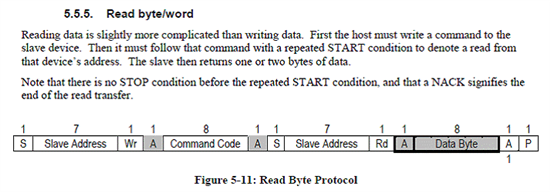
    We are currently trying to read specific registers in the UCD device.This is the approach what we took:

    void Check(unsigned char Dev_Add,unsigned char Reg_Add)
    {
    unsigned char Value=0x00;

    i2c_start();       // i2c starts

    i2c_write(Dev_Add);   // Device Address, in our case 0xC0   <==  (1)

    i2c_write(Reg_add);  // Register Address, in our case 0x27  <==  (2)

    i2c_start();    // Repeated Start <==  (3)

    Dev_Add=Dev_Add | 0x01;  // set 8th bit as read bit,     <==  (4)

    i2c_write(Dev_Add); // Address set to 0xC1   <==  (5)

    Value=i2c_read(TRUE); // Read Value from the register; TRUE sends acknowledgment from Master to Slave. <==  (6)

    i2c_stop();

    }

    Now, we are monitoring the waveform through CRO, and observe that in statement (1), we are getting the acknowledgment.

    Next in statement (2), we are again getting acknowledgment.

    Now, since we ORed the address with 0x01, we get 0xC1.

    I - Now our point of concern is that at statement (5), we get the waveform for 0xC0 and not 0xC1. Also no acknowledgment was received.

    II - Also at statement (6), we get data as 0xFF which means no data was received. Also no acknowledgement was sent from master to slave.

    Now, we need to resolve the issue I and II. Please let us know where the things are going wrong and whether there needs to be a change brought up in the steps/ approach taken.

    Regards,

    Nipun   


  • Hi Nipun,

    I'm pasted the SMBus spec which should be used for Reading byte/word. You should be doing 0xC0, 0x27, 0xC1 and you can get the device ID as 0x41 for UCD9080 and 0x55 for UCD9081.

      Thanks, Spandana

  • Hello Sir,

    We are trying our level best to initiate/configure the UCD9080 through i2c protocol but in vain. We might/might not have succeeded in configuring UCD9080 through i2c write function, which still remains a point of doubt in our mind, since it showed success while writing but reads 0xFF while reading.Our concern increased when we were unable to read the data even from 0x27 which is a read only memory location to identify the device (it showed 0xFF).

    Please let us know the i2c read procedure(in terms of C code if possible and not pseudo code). We are trying to read the location but are getting only 0xFF and no other value from all the locations : user data, configuration memory,rail voltages etc.

    Regards,

    Nipun

  • Our scenario of UCD9080 setup is as follows:

    1. There's an 8 bit micro controller which is interfaced with UCD9080 through i2c protocol.
    2. We are configuring the UCD9080 by writing128 bytes of user data followed by 512 bytes of configuration data through i2c protocol. The values are selected as per our document of Configuration Parameters.xls  and bytes were written as per your document "Programming the UCD9080" 5025.slua441.pdf
    3. The waveform is observed as given in this file. (Write operation section in Waveforms file)
    4. Now to confirm whether bytes have been properly written or not, we try to read the bytes from the memory. (Code block in read operation in Waveforms file)
    5. It reads 0xFF and 0x7F randomly.
    6. The waveform for read operation is as given in this file: (Read operation section in Waveforms file)

    All other queries are listed in this Waveforms file. 

    5340.Waveforms.pdf


    Waiting for your reply,


    Regards,


    Nipun


  • Hi Nipun,

    The scope shots eem to show that the I2C bus is being actively driven but not passively pulled up using a resistor. A low bit level(clock and data) is affected if the bus is pulled to ground and a high bit level is affected by pulling the bus high. The bus should not actively be driven to a high level per the I2c specs. This enables the sharing of the bus by multiple devices. I couldn't quite follow about your question on the 9th pulse. Your host is required to provide the clock(including clocking an ACK or NACK) into the the UCD9080 slave to acknowledge the read operation. Were you able to correctly read the device ID at address 0X27?

    Also it would be great if you can verify the I2C implementation about the signaling levels, timing and protocol against the I2C bus specification I2C Bus Specification

    The UCD9080 makes use of clock stretching if your master code allows for that. your I2C master must poll the SLCK line and it can only drive the SCLK line low once it's high; the UCD9080 will keep the SCLK line low if it needs time to perform its work. The master cannot clock the UCd9080 without regard to its state.

    Thanks, Spandana