This thread has been locked.

If you have a related question, please click the "Ask a related question" button in the top right corner. The newly created question will be automatically linked to this question.

How to adjust output PWM of UC3825

Other Parts Discussed in Thread: UC3825, TL5001

Hi,

I am about to built a 12V to 48V boost circuit using UC3825, the circuit below is my design

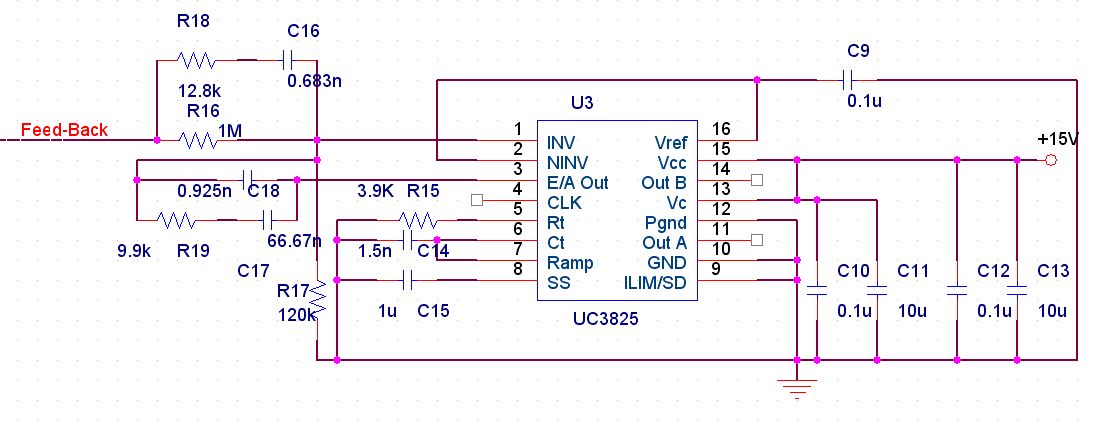
The input of Feed-Back varies from 0-48V(lab DC power supply). The outputs PWM did not change and stay at  46% while increase Feed-Back from 0 to 47V. After the Feed-Back went across 48V, the output PWM changed to 0.  Can someone help me?

  • Move to non-isolated group

  • Siyu,

    Change r16 to 10 K, short C17, run Fb between 2.5 V and 9.5 volts and watch E/A out and the pulse width.

    John

  • Hi, John

    I tried your suggestion, the duty cycle of output PWM vared from 0%  to 46%, but I need a 75% PWM , the E/A out vared from 4.82V to 0V.

    I need to design a type 3 compensator, why I can't change PWM while having C17?

    Thanks for your reply.

    Siyu

  • Siyu,

    I think the toggle flip-flop in the block diagram on page one of the spec should have let you know that the max you will get with this device is 50% duty.

    Go to page 43 and 44 of the attached and select a more suitable part. 

    Power management guide 2011.pdf
  • The datasheet of UC3825, it shows that the maximum duty cycle is 85%, the image below is part of datasheet

     .

    Is it ok to use type 3 compensator on UC3825, why I can't get different duty cycle while using type 3?

    I think I got same problem on IC TL5001, I set maximum duty cycle 85%, if the feed-back voltage is below 48V, the output is 85%, once the feed-back goes beyond 48V, the output PWM goes to 0.

  • Siyu,

    That applies to the comparator not the outputs. Cut that in half for each of the outputs. If you are driving a push-pull design then the total duty cycle will be up to 85% put each half will only see half of that.

    John

  • John,

    Is it ok to use type 3 compensator on UC3825, why I can't get different duty cycle while using type 3?

    I think I got same problem on IC TL5001, I set maximum duty cycle 85%, if the feed-back voltage is below 48V, the output is 85%, once the feed-back goes beyond 48V, the output PWM goes to 0.

    These questions bothered me for a long time, if you can give some help about these, I would appreciate a lot.

    Siyu