This thread has been locked.

If you have a related question, please click the "Ask a related question" button in the top right corner. The newly created question will be automatically linked to this question.

buck design,using LM5088-1/2 to get 12v output

Other Parts Discussed in Thread: LM5088

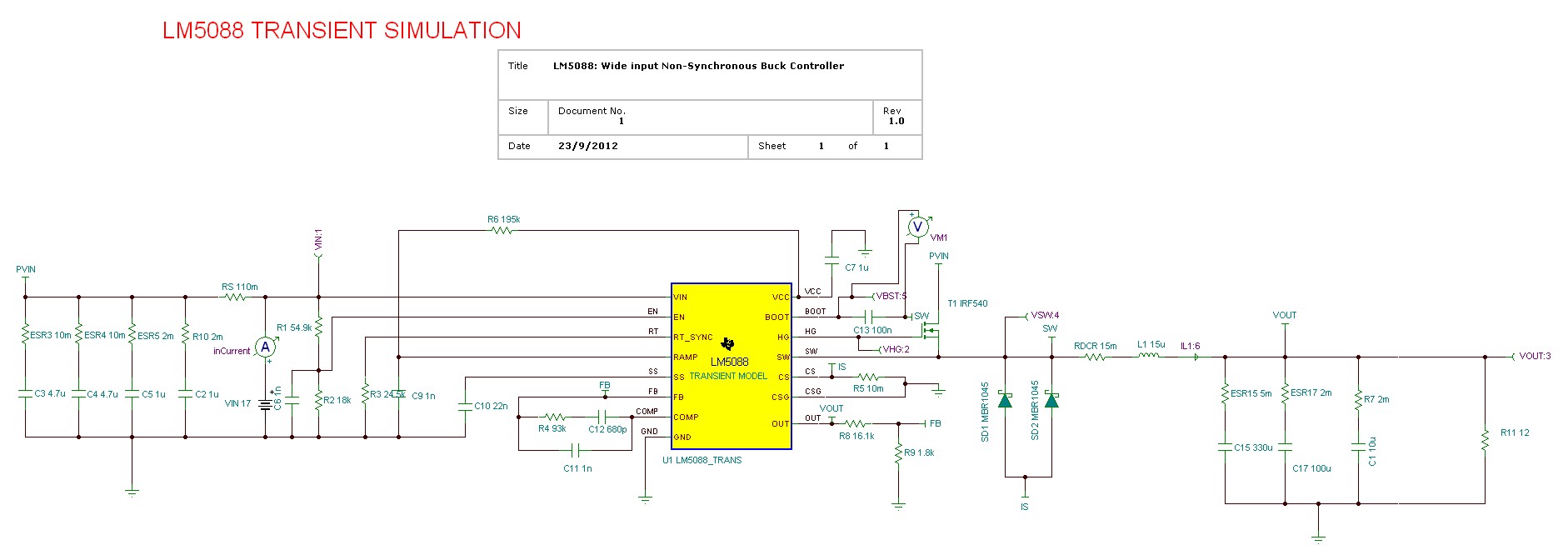
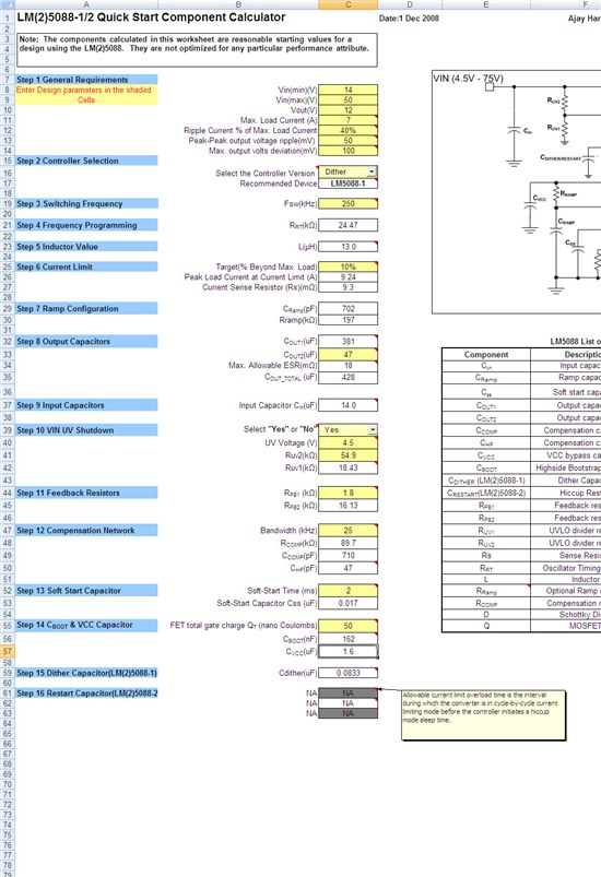
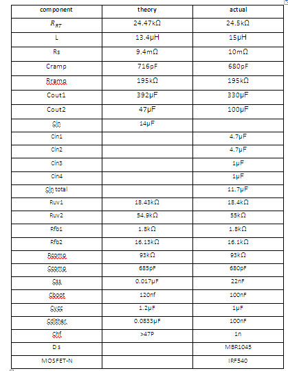
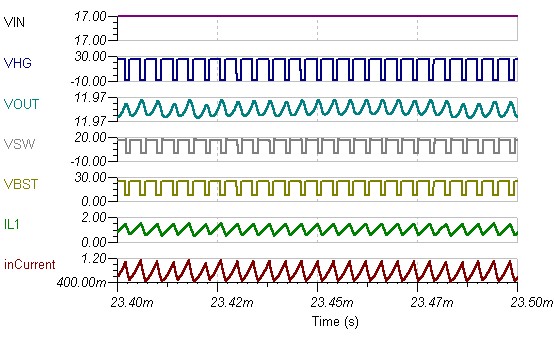
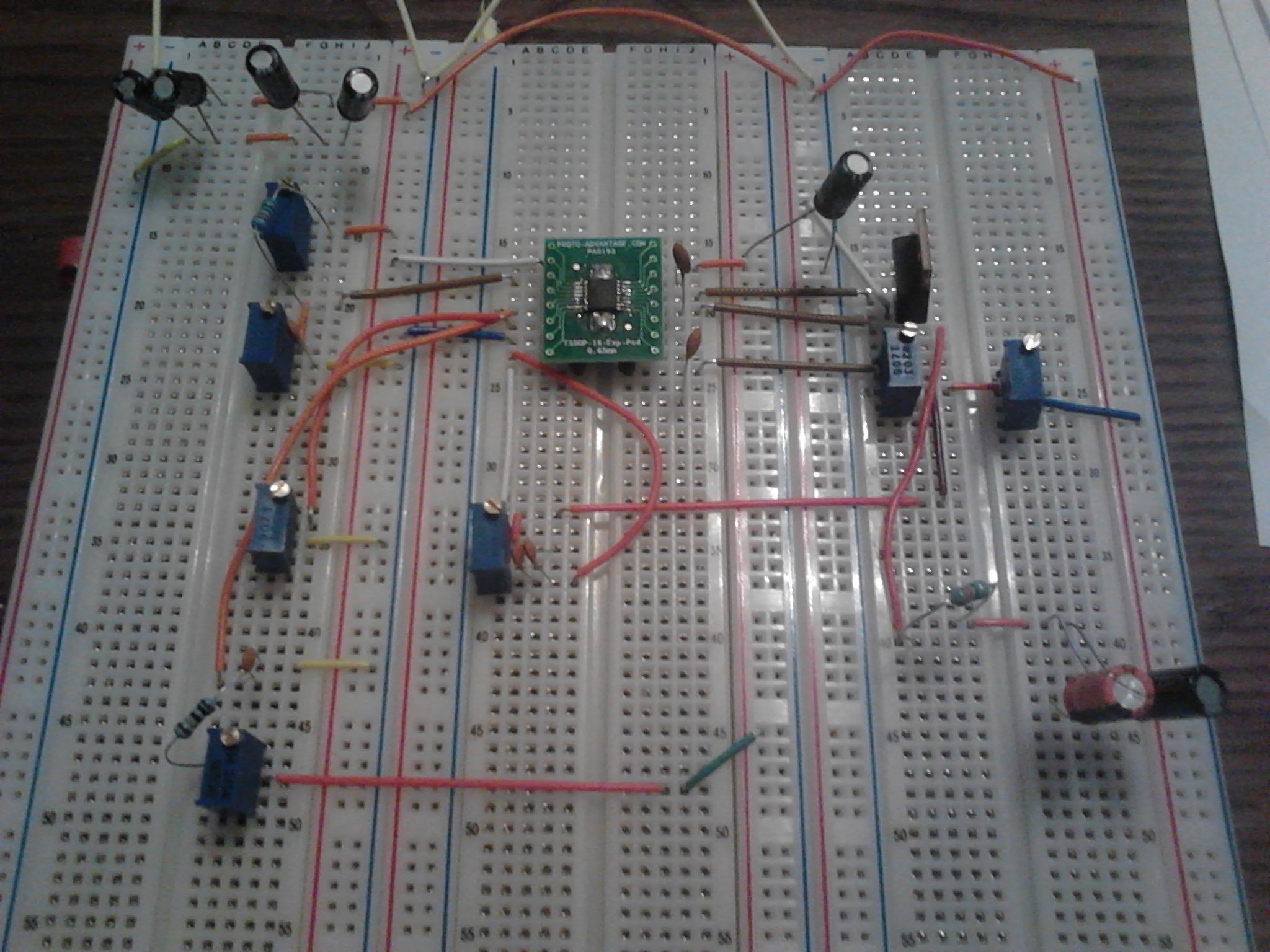
Hi. i'm a student working on a project. i have the LM5088 buck controller. i connected all the parts according to the simulation on Tina and the calculationg xcl.file to get a 12v output Voltage. every thing seems ok on the simulation, but actually it doesn't work. i need your help to understand why is that. and which steps should i take to find the problem.by the way, i connected all the parts on a metrix as shown (it's not all the parts but it's just to show the basic design). i am using parts that are all T/O. the connection of the LM5088-1 is by an adapter to dip. i tryed testing it on the lab, connecting an electronic load. i've tryed ajusting the load from 200 ohms and going down. another thing i've tryed was to connect it to a power supply that gives minimum of 0.03 Amps and i played with the Iin and Vin. still have't got any result.

it looks like there is no switching from the LM5088. how can i be sure that the IC is working ?

which pins should i check and what reading (volts,Amps) am i looking for in the model?


  • Hi

    If you have a voltage meter, please measure the voltage at every pins. This is the first step of troubleshooting. If you have DC bias simulation results, you can compare your mesurements with simulation results.

    I think you might be able to make the board start switching, but it will be very hard to make it working properly. It is recommended to buy a LM5088 EVB from TI's home page and then modify the board if you want.

    Regards,

    Eric  

  • hi Eric,

    i am applying 17-30 volts in Vin and 1 amps and i tryed load values from 0-100 ohms. 

    i am measuring the voltage on every pin, but i see that i don't get the voltage i expect. some times i manage to see 7.8-8v on the vcc

    and some times it goes beyond that to higher voltage.

    i don't see 1.205 v in the FB pin. i think this is the main problem.

     can u advise me on certain voltages that can show me the way to solve my problem?

    why is it hard to make this board working properly? is it an issue of cables and noise ?

    i am using parts that are calculated by the  data sheet,

    first can u look at the parts i calculated and tell me if they are suitable for my plan? can you advise me which values should i try to change if any?

    buying EVB is last resort for me, i don't have much time and money for  ordering one. I'm trying to succeed with what I have right now.

    thanks for your help. 


  • Hi
    Please measure the voltage at every pins referenced to pin #6 and post it. Please describe if any abnormal.
    Regards,