This thread has been locked.

If you have a related question, please click the "Ask a related question" button in the top right corner. The newly created question will be automatically linked to this question.

LM5069 and LM5068, Hot-Swap-Problem

Other Parts Discussed in Thread: LM5069, LM5068, LM5067, TPS2490, TPS2492, TPS2480, TPS24700, TPS24720, TPS24710, TPS2420, TPS2590, TPS25910

Hello.

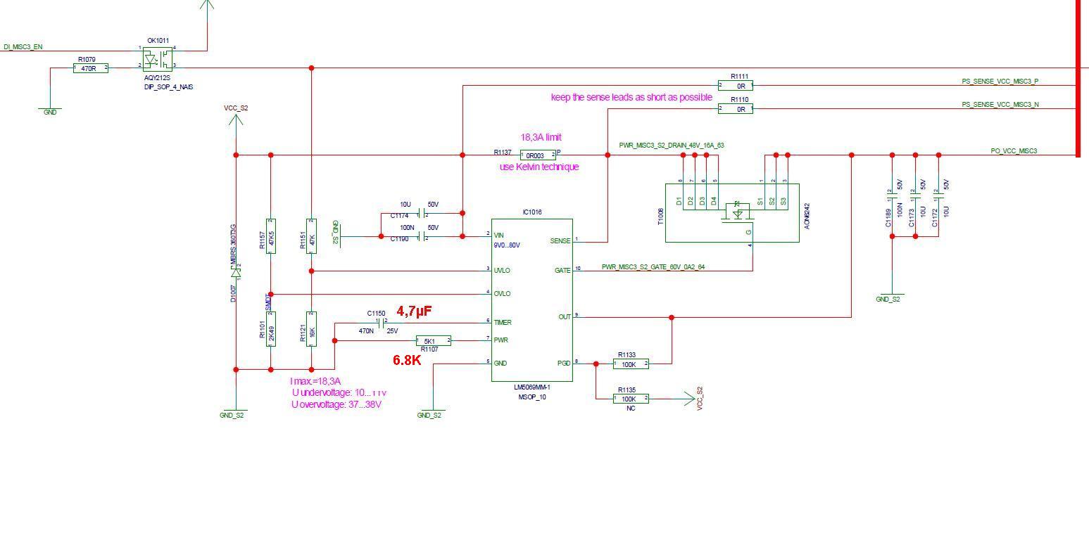
I'm using both hot swap controllers in my schematic, please see attached file.

The power supply is +/-24V at 7.5A, the standard load is the same with 10000µF. Both output voltages come up unloaded without problems.

If I strain both controllers with 25Ohm and 10000µF load, they do not start, the voltage beginns to ramp but the circuit breaker seems to trigger after 400µs at 1,5A.

I changed R1158 to 1mOhm and C1143 to 10µF just for experiment, the positive controller does start but it need some latency time to start again.. The voltage rising process takes 400ms and is very long. The maximum current at this is 7A. I dont understand that because the schematic was designed for much more current and the power supply can deliber 7.5A. Changing MOSFET protection resistor R1102 to 10K doesn't help.

Do you have any idea?

Thank you in advance and I wish you Marry Christmas.

pos_neg_hot_swap.pdf
  • Hi,

    This is a very difficult power up situation.  The power limiting feature of the device will reduce the input current to roughly 1.5A, and to charge 10000 uF  at 1.5A will take 160 ms, by my calculation, without a load.  Add an additional load and it will take even longer.

    Once it powers up, there should be no reason the device goes into current limit at 7.5A, though.  Can you send a scope shot of the device going into current limit?

    Regards,

    MIke


  • Hello Michael,

    thank you for reply,

    1. that means if the timer capacitor is only 470nF, the device cannot load 10000µF and will turn off prematurely, is that right? The TI-Webench shows me something about 22µF.

    2. 7A was the peak current of start up process with 25Ohm and 10000µF. The current afterwards is only 1A.

    I will be at my workplace after christmas and only then I can send a scope shot from that design.

    Best Regards

  • Hi Vitali,

    Yes that is true.  During startup, the device can either go into current limit or power limit, depending on which mechanism has a lower current limit.  If the power limit is set to 50W, and VIN = 25V, then at startup the device will limit the current to 2A, but if the current limit is set to lower than 2A it will limit at the current limit.  As VOUT goes up, the power limit will allow more current to satisfy the constant power across the FET.

    During power limit or current limit, the timer pin will begin to ramp until it hits 4V, after which it shuts off the FET.  The timer cap. will determine how long this time is.

    Let's continue this discussion after Christmas- happy holidays.

    Best Regards,

    Mike

  • Hello Mike,

    I hope you had restfully holydays.

    I've got further guestions for that schematic attached as pdf file.

    1.LM5069. If I change Ctimer to 22µF for big loads (47000µF and 25 Ohm parallel) I obtain a very long insertion delay of 16 seconds. Is there any way to avoid that initiall delay?

    2.I've noticed that LM5069 and LM5068 do not start simultaniously. LM5069 starts the insertion timer when the power supply is available and LM5068 starts the insertion timer only when the device is activated via undervoltage pin. Is that right?

    3.For the negative hot swap controller I did following changes, in despite of them the controller doesn't start, please see the attached screen shot:

    Do you have any idea?

    Changes:

    Rsense=2,5ms, Ctimer=22µF

    Load: 47000µF and 25Ohm parallel

    CH1: V load 24V,  CH2: Vin 24V, CH3: I load

    Thank you in advance

    Vitali Lach

  • Hello Vitali,

    The holidays were nice, thanks.

    1) Unfortunately we do not have a solution to separate the fault timer from the insertion delay period.  If you could add current to the timer node during the insertion delay period, it would help speed it up, however the device does not provide an external signal to indicate the insertion delay period.

    2) You are correct.  The LM5068 functionality is slightly different, it will go through a delay period after a UVLO flag.  The device that more closely models the LM5069 functionality on the negative side is the LM5067.

    3)  Let me see if I'm following the scope shot:  I see V load at 0 V, VIN at 24V, then the load current begins to increase, and as that happens, VIN droops.  Then at some point, the pass FET shuts off.    Is it possible VIN is going below the UVLO threshold and the device is turning off?  In this configuration, the device will go into current limit at 20A however the only response would be that the timer node begins to rise.  At 40A it will attempt to regulate the current by controlling the gate of the pass FET, however it does not appear the current gets to that point.

    Can you repeat that scope shot with the TIMER node and the GATE node plotted?

    Regards,

    Mike


  • Hello Mike,

    thank you for supporting me.

    I noticed following things in the schematic:

    1.LM5068, I cannot change the start up current with Rsense: 2.5, 7, 10mOhm, the current is always 10A. Load: 25Ohm with 47000µF, please see attached file. 10A current is to much for power supply, the device should regulate (sink) the current, shouldn't it?

    CH1: power input

    CH2: power output

    CH3: Ct-Voltage

    CH4: output current

    I am not able to attached several files, therefore I will make three posts here.

  • 2.LM5069, I noticed that sometimes it goes into fail mode when device turns off and afterwards quickly turn on again. I have to wait certain time to start again. Please see attached file

    CH1: power input

    CH2: power output

    CH3: Ct-Voltage

    CH4: output current

  • 3.LM5069, this design is for 48V, T1008 become defective at turn on process. Ct changed to 4.7µF, Rpwr to 6.8K.

    The power supply is 48V, the load: 48Ohm with 1200µF.

    Do you have any idea? I would appreciate your suggestions.

    Best Regards

    Vitali

  •  

    Hi Vitali,

    This is a response to your last request, I will need to research a few things get to the other 2 tomorrow morning.

    Your FET is most likely failing because at startup the device is exceeding the SOA, and you can't necessary tell because some FET companies do not take into account high voltage breakdown effects of vertical FETs.

    The following app. note is a good description of the different regions of an SOA.  Note that some companies do not specify the "thermal stability limit" as seen on page 7.  Unfortunately it means you may need to switch to a FET in a larger package to survive the startup event, or reduce the power limit.

    http://www.infineon.com/dgdl/Infineon+-+Application+Note+-+Linear+Mode+Operation+and+SOA+Power+MOSFETs.pdf?folderId=db3a3043156fd5730115939eb6b506db&fileId=db3a30433072cd8f0130b63abece21ad

    Hope this helps,

    Mike

  • Hi Vitali,

    The LM5068 does not have constant power regulation, and the current regulation does not occur until there is 100 mV across Rsense.  You should have seen it begin to limit the current to below 10A when Rsense was larger than 10 mOhm.

    Another option is to increase the size of the capacitor on the gate.  The rise rate that is set in the scope plot you are showing is the result of a 60uA current source charging into a 22nF capacitor.  A larger capacitor would decrease the rise rate and therefore lower the current.

    I hope this helps,

    Mike

  • Hi Vitali,

    Regarding the LM5069 quick turn off/on:

    In this case, it appears the timer cap. is not fully discharged when it begins to turn on again.  Then there is not a sufficient amount of time for the turn-on procedure to occur.  The timer cap. needs to be discharging long enough to allow the timer to ramp again before the time-out will occur.  If you switch the UVLO/enable at a frequency that has a period shorter than the required time for a normal startup and timer discharge, then you will hit a fault event, and the the device will go into retry timing mode before it starts again.

    I hope this helps,

    Mike

  • Hi Mike,

    yes, that helps a lot, thank you very much, I think all questions are answered for that schematic.

    Could you recommend another TI-devices (Hot Swaps, without Timings, like a switch) for that?

    Power supply: 12V...36V, if not feasible 18V...36V.

    Load: 47000µF and 25Ohm parallel, if power is up the current can increase to 6...10A.

    Best regards

    Vitali

  • Hi Lach,

    TI also has

    1) TPS2490/1, TPS2492/3 for input voltage from 9V - 80V with power limit, inrush, analog IMON CFLT

    2) TPS2480/1 for input 9V - 26V hotswap with I2C monitoring power, voltage and current

    3) TPS24700/TPS24710/TPS24720 for input voltage from 2.5V to 18V with power limit, analog IMON CFLT and lower current sensing voltage of 25mV

    4) TPS2420/TPS2421/TPS2590/TPS25910 for input voltage form 3V to 20V 5A integrated FET hotswap controller with power limit, IFLT, ILIM, CFLT and thermal shutdown.

    Zao

  • Hello Zao Yang,

    thank you very much for that!