This thread has been locked.

If you have a related question, please click the "Ask a related question" button in the top right corner. The newly created question will be automatically linked to this question.

Resistors selection and PCB layout of TPS7A3001/TPS7A4901

Other Parts Discussed in Thread: TPS7A30-49EVM-567

Dear all:

Recently I am trying to use TPS7A3001/TPS7A4901 for providing clean and stable +5 and -5 V power for my PCBs. I am aware that the output voltage is adjustable by changing the values of external resistors which is connected between the OUT pin and GND. After reading the datasheet, I have some questions:

1, basically I know one rule is that the current should be greater than 5 uA. But is there any criteria for selecting proper values of resistors? e.g. I can choose two resistors of 10 K and 20 K or 100 K and 200 K to get the same desired voltage, what is the difference between these two selections?

2, in the datasheet of these two devices, I found: it is recommended that the board be designed with separate ground planes for IN and OUT, with each ground plane connected only at the GND pin of the device.

 While in the datasheet of the evaluation module TPS7A30-49EVM-567, I found the ground planes of IN and OUT are not separate from each other. 

I am wondering which rule I should obey when designing my PCBs? And why 

I will appreciate if anyone could help me, many thanks in advance.


Cheers,


Ruo

  • Hi Ruo,

    1) Please see the below article that goes into detail about changing the resistor divider.

    http://www.ti.com/lit/an/slyt469/slyt469.pdf

    2) Split ground planes is a general board design technique for ALL LDOs and this comment on split ground planes are in some datasheets and left out on others. This is mainly for noisy inputs (such as switchers) where the di/dt noise currents can be somewhat isolated from the load. If the customer has a battery at the input, it may not be necessary. In terms of PSRR, you typically see an improvement of 2dB. You may want to order the EVM and evaluate it on your application to see if it meets your specs.

    Regards,

    Darwin

  • Hi Darwin:

    Thanks very much for your reply. After reading the article you provided, I summarized it as follows:

    1, large resistors are needed to increase the power efficiency;

    2, large feedback resistors affect the output-voltage accuracy;

    3, more noise are generated by resistors and coupled into the device;

    4, with the same feed forward capacitor, smaller resistors may lead the system into unstable. 

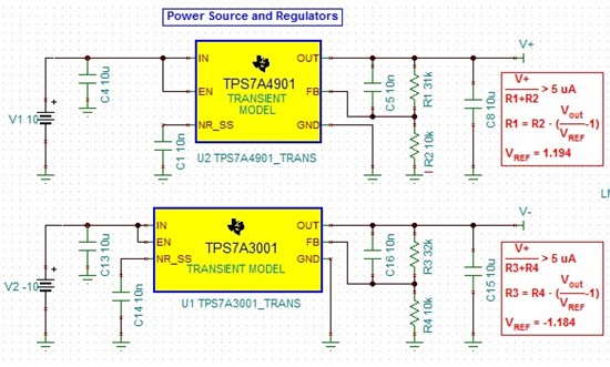
    I am using power supply to power my PCB so the efficiency is not a big concern while I want to keep a low noise level for the whole PCB. I have attached my design using two devices. The input voltage is +/- 10V and the desired output voltage is +/- 5V. The feed forward capacitor is 10 nF. Could you please check if the system is stable for the values of resistors as shown below? 

    Thank you very much!

    Ruo

  • Hi Ruo,

    Your design looks good! I see no issues with using the resistor dividers above.

    Regards,

    Darwin

  • Dear Darwin:

    Thanks very much for your reply. I have one last question and will appreciate if you can help me:

    From the article you provided, two frequencies: zero frequency and pole frequency are discussed to evaluate the stability of the device. I calculate the zero frequency based on the values of my circuit, which is 513 Hz. Pole frequency is calculated to be 2.1 MHz. However, in the article, these frequencies are calculated to be 19 KHz and 60 MHz. My question is how could we evaluate if the device is stable based on these two frequencies in this case? For example, should zero frequency be smaller than a certain value to make the device stable.

    Many thanks in advance.

    Regards,

    Ruo

  • Hi Ruo,

    The section you are referring to is typically for switch mode power supplies where they use different control techniques where a feed forward cap is required. The example also uses a buck converter for analysis. 

    For LDOs, the feed forward capacitor increases the devices performance such as transient response and noise. Therefore, you should have no issues with having 10nF for your feed forward cap.

    Regards,

    Darwin

  • Hi, Darwin:

    Thank you for your reply. All problems are solved. 

    Cheers,

    Ruo