This thread has been locked.

If you have a related question, please click the "Ask a related question" button in the top right corner. The newly created question will be automatically linked to this question.

TPS40170 start-up current limit issue

Other Parts Discussed in Thread: TPS40170, TPS40422

I have a design based on the TPS40170. It is a 24V to 28V input design with a UVLO voltage of 16V and output of 1.2V at 3A. I'm finding that the supply is unable to start unless the input voltage is around 30V or higher. I've measure the SW node and am attaching some screenshots to show the results.

"when I crank up the input voltage above ~30V"

As you can see, the rising edge is pretty good with no ringing, but the falling edge (HS-FET turning off) shows considerable ringing. This seems a bit odd, but this is the case. I believe that what is happening is that the noise from the ringing is causing the controller to sense an OCP or SCP fault and then turning off the supply. It continues to 'hiccup' until the input voltage is high enough, at which point the rail comes up as shown above.

I have several instances of the same PCB (new prototypes) and have observed some variability in when the supply comes up, but in all cases the overall behavior is the same. Increasing the ILIM resistor can allow the supply to work, but the amount that Rilim needs to be increased varies from board to board. Moreover, I don't want to hike up the current limit to a high value just to get things to work.

Please note that I also have three other supplies, 3.3V, 5V, and 12V that use the same controller and topology. They all use the same FETs and have very similar layouts and derive from the nominal 28V Input. In the case of these three supplies I see the same undershoot when 28V is applied to the board, but shortly after initial application of power the undershoot and ringing goes away and the SW waveform looks fine. Please see the sequence of 3V3 screen shots.

3v3 startup pulse  " perhaps during softstart"


still 3V3 startup


3V3 after startup, Note that there is no undershoot

The same phenomenon is observed on 5V and 12 V as well as 3V3

Also , we observed that the ringing frequency is common to all supplies (approx 150MHz)

I don't fully understand why this occurs only while the supplies are starting up. Please enlighten me. I understand that the layout may need to be examined and changed, but I'd like to get these boards working so as not to stall other developers who need the boards. I may have to increase the ILIM setting to achieve this, but I'd like to try other options as well if they exist.

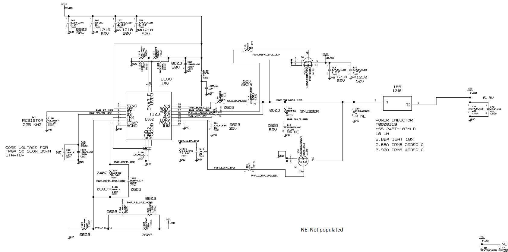
5618.TPS40170-1V2-Schematic.pdf 

Note : NE stands for" not populated"

 Thankyou

Ashok/ Kevin

  • Hi Ashok,

    I recommend trying to populate the snubber and adding a 4.7Ω series resistor to the gate drive of the high-side FET. If there isn't already, I also recommend adding some bulk capacitance on the 28VDD supply. In addition, like you mention layout would be good to check. The placement of C962 and C963 are critical to minimize the high di/dt current loop.

    Is there a load on the output for these measurements? Also what bandwidth was used on the oscilloscope with these measurements?

    Best Regards,
    Anthony

  • With another look, I have some doubts in the stability with the selected compensation components. I recommend using the Compensation Calculator Tool which is located on the TPS40170 product page to test this out. From my testing, I saw the two added pole to be at much too low of a frequency and the model shows negative phase margin at the crossover frequency.

    Please see the link below for the excel sheet I worked in.

    1715.TPS40KType III Loop Stability kVenable_sluc263c.xls

    Best Regards,
    Anthony

  • Thank you for the suggestions Antony,

    We do have Bulk decaps for the 28V , and also we have the smaller decaps placed right below the Switch node.

    We tried adding series resistance to the High side and/or Low side gate drive. But still the switcher doesnot turn on if the ILIM is set to the nominal value.

    As you can notice the pulse width of the converter is less than the nominal value. It looks like the high side fet is swithced off prematurely .  Can this happen for any other reason than than OC or short ckt.

    We will check the stability calculation using the .xls


    Thankyou

    Ashok


  • Hi Anthony,

    The stability comes out fine with the 1715.TPS40KType III Loop Stability kVenable_sluc263c.xls. Please note that we had 2x 47uF and 1x470uF  ceramic caps with low ESR as the loap capacitance (although schematic symbol shows electrolytic).


  • The loop does look much better with the electrolytic capacitor added. Please note the selected IC in the screenshot shared was the TPS40422. The loop changes slightly but is still stable if changed to the TPS40170.

    Back to my previous questions, were the switching waveform measurements taken with full bandwidth and what was the load current for the previous screenshots?