This thread has been locked.

If you have a related question, please click the "Ask a related question" button in the top right corner. The newly created question will be automatically linked to this question.

LM5116 turns off

Other Parts Discussed in Thread: LM5116, LM5575, LM5576, LM5010

Dear Community:

I have built a regulator based on LM5116

Vin from 8 to 72 V.

Vout  is 5 V.

Iout is 1 A.

The regulator works well when Vin is from 8 to 30 V. But, when I ramp more than 30 V, the LM5116 stops working (Vout = 1V).

I have tested some values for the feedback components trying to compensate, but this produced no change.

The simulation in Tina indicates a well performance for voltages over 30 V, but it really does not happen in practice.

I attach here the diagram of the regulator and I will attach any signal you consider helpful.

6567.3_POWER_REGULATORS_P1.pdf

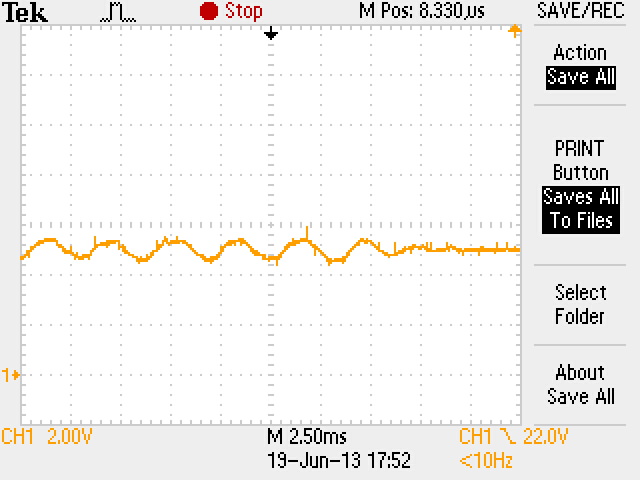
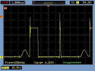
I show here the signals in LO and HO at VIN = 30 V and  VIN = 31.2 V, when is the transition to fail.

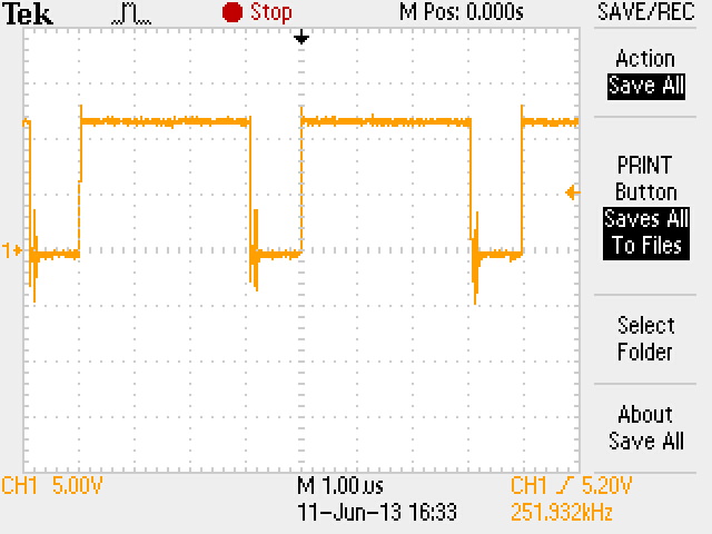
LO at 30V is still regulating.

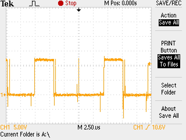
LO at 31.2 V. The pulse in the middle was skipped.

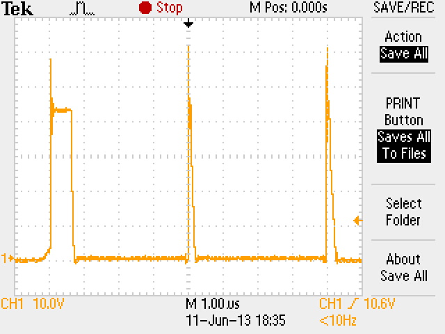
HO, gate of High side mosfet. Only the fisrt pulse is complete.

Note that is NOT the same time scale for all charts.

Thank you in advance for your feedback

Zeus

  • Hi

    I guess that a noise causes such a wrong pulse. Please try a strong snubber.

    Also, replace D303.

    Regards,


  • Eric:

    Thank you for your feedback.

    I soldered the components of the snubber and tried many values to get the best result. Now it controls up to 41 V at input instead  of 30 V. The objective is 72 V.

    The signals remain the same. Some pulses are skipped. 

    When the input is around 27 V the output is oscillanting from 4 to 6 V at a frequency of aprox 330 Hz.

    That oscillation is due to the skipping pulses.

    I changed the schotkky diode as suggested for a switching diode (both supporting up to 100 V and 3 A) and there were no change in signals.

    The webench does not allow simulating with a buck inductor of 47 uH, since it is limited to 40 uH. But I cannot find that limitation in the datasheet.

    If you require  signals at another node I will send them.

    I will appreciate your feedback.

    Zeus

    Voltage at the output capacitor due to pulse skipping.


  • Dear support team:

    Thanks to the kindly help of Howard Chen now I can simulate with Webench. I have placed the components with the values suggested by Howard. But I still have the same problem. The regulator stops regulating at 40 V.

    The signal at HO looks like the figure below. Maybe this signal gives information about of the problem.

    Another problem that I detected is that although I connected pin DEMB directly to the GND in Rs, the LO pin is commutating, while LO is supposed to be always at 0 V.

    When I connect the snubber, the output has oscillations at some input levels, for example when Vin = 27 V, Vout oscillates between 4 and 6 V.

    Fig. 1. Signal at HO. Vin=30 V. No snubber. DEMB at 0V (but LO was oscillating).

    I will appreciate your feedback.

    Zeus.

  • Hello Zeus,

    I have recently built a WEBENCH design for a customer with these input conditions: 7-80Vin, 5Vout, 6A Iout at 260kHz.  I used the LM5116 demo board for it and it worked pretty well.  Can you share your board layout here for us to review?  Also, please visit the LM5116 applications note which shows scope shots of a normal operating circuit and that's a good reference. http://www.ti.com/general/docs/lit/getliterature.tsp?literatureNumber=snva226c&fileType=pdf 

    Since your design is only for 1A load, it seems a bit over designed using the LM5116.  We have some regulators (LM5576, LM5575, LM5010) can work for your design.  I don't want to steer you away from using the LM5116 now but in the future, you should consider the regulators because their switching elements are integrated.  They are much simpler to work with.

    Lastly, it looks you are using either Altium or Protel, I have the source PCB layout files in Altium and I will share it with you.

  • Howard:

    Thank you for your kindly answer.

    Below I post the loyout of the section of the board where the Power supply is located. I couldn't get to show the viasholes but they are present where required.

    In this design we have used LM5575 where the voltage is about 20 V and it worked fine. The power supply here referred will work with a nominal voltage of 72 V but it could have transients up to 100 V.That's why we can not use directly the alternative integrated circuits you suggest.

    I hope the next pcb figures can help.

    Fig. 1. Top components silk screen

    Fig. 2. Top layer. Here can be seen that the DEMB pin is connected directly to GND plane with a vias. But the track was cut and a wire was connected directly to the negative teminal of Rs.

    Fig. 3. Firts internal layer.

    Fig. 4. Second internal layer.

    Fig. 5. Bottom layer

    Fig. 6. Botton component silk screen

    All your suggestions are wellcome.

    Ask for additional information that could be useful.

    Zeus Escudero

  • I have soldered the the components with values that you suggested, and it didnot work.

    I have redesigned the PCB Layout and soldered again the values you suggested and it worked ok.

    Thank you for your support.

    Zeus