This thread has been locked.

If you have a related question, please click the "Ask a related question" button in the top right corner. The newly created question will be automatically linked to this question.

TLV1117-5 Noise

Other Parts Discussed in Thread: TLV1117

Hi everyone ,

I am running into some trouble with our 5V regulator. I am using the TLV1117-5 DCY with :

Vin : +12VDC with a capacitor 100uF, 25V, X5R (ECA-1EM101)

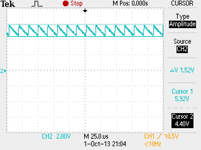
Vout : Noisy 5V oscillating 4.40V and 5.91V. I use two caps. A 47uF 16V aluminum capacitor (REA470M1CBK-0511P) and a 0.1uF 25V X5R ceramic capacitor (06033D104KAT2A).

The output resistive load measured is 1Kohm.

I have attached the screenshot of the output. 

I have followed the footprint guidelines from the chip datasheet.

The described problem occurred twice within two months - I have replaced the part once and it was working fine until the problem occurred again. 

Any thought, suggestions is welcome.

Thanks.

 I also use the 3.3V and 1.8V regulators using the same capacitors and I don't have any issue on the same board.

  • Cedric,

    In the waveform, I see 8 cycles in 125uS (5divsions). This is 64kHz. The Xc of the 47uF capacitor is 53mOhms. The aluminum capacitor has a ESR way higher than that, so it zeroed long before 64kHz. The 0.1uF ceramic output capacitor plus any other bypass ceramic caps in the circuit will have an Xc at 25 ohms (for 0.1uF) which will add an output pole that is active at 64kHz when the loop gain drops to unity (0dB).

    To support the ceramic capacitors on the output, the main non-ceramic cap will need to reduce more TLV1117 gain before it's ESR creates a zero. Increasing the main capacitor's capacitance and lowering it ESR will help. A 100uF tantalum for example.

    There is no limit to the increase in capacitance allowed but there is a limit to the reduction in ESR. If the ESR is too low then the TLV1117 gain will drop to unity before the main capacitor zeros and oscillation can occur. 

    For future designs, I suggest a ceramic main capacitor with a series resistor added (0.2 to 0.5 ohms). This allows more flexibility for fine tuning the stability.

  • Thanks for this interesting answer and your recommendations. I will try a Tantalum 100uF 16V with 0.1 ohms ESR. I hope this will fix the problem. 

    Update :  Yes, it did the trick. Thanks for your help.

  • Cedric,

    You can check the stability by performing a load transient test on the output and monitor the regulator response.
    A pulse generator with series resistor makes a simple transient source.

    Simplifying Stability Checks.pdf
  • Ron,

    Thanks for the pdf, very useful.

    The interesting thing is that, prior to observing this "bug", we have run some stress test on the chip to verify that in our circuit it would work with variable loads (we did step loading as described in pdf). All tests were satisfying and the regulator was stable. Also, the first time, when we have replaced the chip because we thought the chip was defective it fixed temporarily the problem.  Something over time must change the stability of the regulator... temperature ?