This thread has been locked.

If you have a related question, please click the "Ask a related question" button in the top right corner. The newly created question will be automatically linked to this question.

Cannot power on after DEV_OFF shutdown TPS65910

Other Parts Discussed in Thread: AM3358, TPS65910, TPS65910A

Hi,
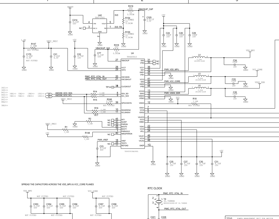
Currently we are experiencing the following issue with our system which has an AM3358 processor in conjunction with a TPS65910 (TPS65910AA1RSL) power management chip. 

The system and processor powers up ok when we switch it on, but if we shutdown the system by setting bit 0 (DEV_OFF) of DEV_CTRL_REG (0x3F) to 1 using I2C communications, the system shuts down as expected, but we cannot then switch it back on again immediately.  We are also using the TPS65910 as our system RTC, which is backed up by a superCap to maintain the RTC for a period of time between system battery changes.

Investigations have led us to conclude that it is when this superCap has charge that we are unable to switch on the system.  Discharging the superCap manually allows us to recover and switch the system on.  Also leaving the system off for a long period of time (naturally discharging the superCap) works as well.

Here are the contents of what I think are relevant registers 2 seconds prior to the shutdown command being sent to the TPS65910:

PMIC_INT_STS_REG register = 0x12
PMIC_INT_MSK_REG register = 0x2
PMIC_SLEEP_KEEP_RES_ON_REG register = 0x0
PMIC_DEVCTRL_REG register = 0x0
PMIC_THERM_REG register = 0xD
PMIC_VRTC_REG register = 0x1
PMIC_REF_REG register = 0xD
PMIC_RTC_INTERRUPTS_REG register = 0x0

I guess even though we are setting the DEV_OFF bit of the DEV_CTRL register, instead of the OFF state, do we actually go direct to the BACKUP state if we have backup voltage on the super cap which is connected to VBACKUP; the datasheet says the DEV_OFF bit is cleared when it enters the OFF state, if it did go direct to the BACKUP state would the DEV_OFF bit be cleared and hence not be the cause of power on prevention?

Also, I have tried changing my code to mask and clear off the interrupts in INT_STS_REG, and with the INT_STS_REG register reporting 0x00, we still get the issue where we cannot power on immediately after a DEV_OFF triggered shutdown.

Does anyone have any thoughts?

Thanks

John

  • can you please let me know what is the voltage on backup pin , PWRON pin and PWRHOLD pins ?

    Is any of the other device off conditions are still existing when you try to boot up the device ?

    May be ot would be good if you can please share the schematic.


    Thanks,
    Puneet

  • Hi Puneet,

    thanks for your response.  I have put the requested voltages in the table below.  Our current setup involves using a bench PSU to supply power to our board, this power results in a supply of 5V being applied to VCC7 while our button is pressed, once we power on successfully the 5V is latched permanently through the voltage being supplied through SW1 pin on the TPS65910A.  We are using PWRHOLD as the signal triggered by our power button, but PWRON seems to copy PWRHOLD's behaviour.

    State PWRON PWRHOLD VBACKUP VCC7
    PSU Off - Supercap Charged 0V 0V 2.75V (at time of measurement, reduces over time from 3V) 0V
    PSU Off - Supercap Discharged 0V 0V 0V 0V
    PSU On 0V 0V 3.1V 0V
    After successful Power On around 5V around 5V 3.1V 5V
    After DEV_OFF=1 Shutdown (PSU On) 0V 0V 3.1V

    0V


    When the Supercap discharges and VBACKUP goes to 0V, we can press the power button and the system powers on successfully, but while the Supercap has charge we cannot.

    Out of the power-on disable conditions, I cannot tell if DEV_OFF bit is still set as our main processor is off and we cannot read any of the registers on the TPS65910.  If we successfully went into the OFF state which it looks like we have then this bit should be cleared automatically.  I think we are ok for the other conditions.

    One thing to mention which I find strange is that the PWRON signal, although shown in the schematic as Not Connected, it seems to behave exactly as PWRHOLD does.

    I will do another post showing the schematic.

    Thanks

    John


  • Hi,

    I have attached the relative areas of the schematic.

    PMIC TPS65910A: 2845.PMICSchem.pdf

    Power Button: 1663.PWRButton.pdf  SW2 is the push button.

    PRE_AVCC and VBATT are 15V, our board can have its main 15V power supply as a either coming from mains/bench PSU or from a battery.


  • Hi John,

    I see on the schematic PWRHOLD is connected to 5v and when you write DEVoff =1 the 5v supply goes off. i am assuming after DEV_off you apply 5v on VCC& and PWRHOLD also , right ? This should wake up the device even without pressing poweron button as PWRHOLD is wake up event for device.

    Also, on the schematic i see PWRON pin is NC, where is the push button connected ?


  • PWRON is active low sinal but PWRHOLD is active high, PWRON just boots the device but PWRHOLD boots the device as well as keep s the device on. So to keep the device active PWRHOLD is required.

  • Hi Puneet,

    pushing the push button SW2 causes 5V line connected to PWRHOLD to go to 5V, I can see on a scope that PWRHOLD goes up to 5V for as long as I press the button, VCC7 also goes to 5V when I press the button, but when I release the button both these PWRHOLD and VCC7 go back to 0V when we cannot power up after applying DEV_OFF=1.  PWRON signal does exactly the same as PWRHOLD and VCC7, which surprises me as it is indeed listed as NC in the schematic.

    On a successful power up (when the superCap has been discharged), VDD_MPU comes up and holds PWRHOLD, VCC7, PWRON high at 5V.

    Thanks

    John

  • John,

    I understand the PWRON behavior as it has an internal puppup to VCC7 so this is ok as it goes high and low with VCC&.

    But i dont understand why VCC7 and PWRHOLD are hot staying high when button is relased as these are the input supplies. independt of the PMIC state they should stay high.

    Thanks,

    Puneet

  • Hi Puneet,

    Sorry for the delayed response.  I am going to have further discussions with the hardware engineer who designed the circuitry based on your questions.  For PWRHOLD and VCC7 to stay high in our circuit, we need VDD_MPU to be available and this only happens when the power on sequence is successful as it comes from the SW1 signal of the TPS65910.

    Do you have any thoughts on how the VBACKUP having a voltage could affect things?  One of the key points in this issue is that the problem only exists while the Supercap supplying VRTC into the TPS65910 has charge.

    Thanks

    John

  • John,

    OkI undestood what the circuit is doing now. Thanks. Did you try DEVOFF_RST bit, Is that bit doing the same ?

    when you monitor the VRTC voltage during the turin off seqnce does it ever go to zero and come back up again. or always stays on . This can tell if the device is in off state of backup state.

    Thanks,

    Puneet

  • one more question , is this loop from PWRON on to MPU back to PWRHOLD how long is this duration.

    PWRHOLD has to be high within 1 sec of the PWRON press.

    After writting dev off bit , can you GND PWRON pins of pmic for short duration to check if the PMIC turns on. Need to maintin 5v on VCC7 during this.


  • Hi Puneet,

    Yes I have tried the DEV_OFF_RST as well, and the it behaves in the same way as the DEV_OFF bit.  Monitoring the VRTC, while I set DEV_OFF, I see that it stays at 1.8V.  Which state does this suggest the device is in?

    Tomorrow, I will try out the grounding of the PWRON signal and let you know what happens there.

    Thanks

    John

  • Hi John,

    If VRTC stays aroung 1.8v the device is in backupmode.

    Thanks,

    Puneet

  • Hi Puneet,

    so sorry for my delayed response, some other activities have taken priority recently.  I worked with the hardware engineer to to ground the PWRON pin as you suggested, we grounded it whilst pressing our power button on, but the issue still remained in that it did not power on. 

    You said to ensure that we had 5V on VCC7 whilst doing this, the 5V was applied to VCC7 whilst the power button was pressed as is the case with our particular design.

    Do you think our problem is that we are stuck in the backup state?  In order to get out of BACKUP state, we need to get back to the OFF state by applying 5V to VCC7 again so that MB (main battery) is above the voltage threshold, then we can get to ACTIVE state by pressing the power button to cause PWRHOLD to go high.  In our design, the pressing of the power button causes the PWRHOLD and VCC7 to go to 5V so these two conditions could happen either simultanesouly or very close to each other.  Could there be an issue with timing or order between our PWRHOLD signal and when 5V is applied to the VCC do you think?

    Thanks

    John

  • Hi John,

    I dont expect PWRHOLD and VCC7 timing should be a major concern because PWWRHOLD is a wake up event it should boot up the device always as soon as it goes high. I suspect device is in backup domian here. Can you please try to remove the bakcup battery and check the device wake up every time , if so then we need to find a another way of to shut down the device and wake up on PWRHOLD event.

    Thanks,

    Puneet

  • Hi Puneet,

    we have done this modification already by removing the voltage on the VBACKUP and yes it powers up every time; this has been a temporary fix for us when required. 

    One thing I perhaps haven't mentioned before, is that sometimes it has powered up successfully with the VBACKUP in place after setting DEV_OFF.  So it is not a full 100% occurence of it not powering up, but it is very unusual for it to power up once we have done the DEV_OFF shutdown.

    If you do have other thoughts on how we could initiate a software shutdown that would be greatly appreciated.

    Thanks

    John

  • John,

    Do you see any correlation with the VBACKUp oltage when the device did not powerup,. Like below or above 2v ?

    Thanks,

    Puneet

  • Hi Puneet,

    when we have the issue, we manually ground the Supercap output to discharge it so that we can power on again quickly and I can tell you that we don't have to dischrage it all the way down to 0V. Hopefully tomorrow, I can get time to check the highest voltage of VBACKUP that allows for a successful power up. 

    From the top of my head, 2V does seem familiar, but I will check and let you know.  Is there a specific reason why you mention the 2V value? 

    Thanks

    John

  • Hi John,

    There is a POR in the device with resets around 2v, if all the in votlages go beloew 2v including backupbattery everthing is reset inthe device . Same as no supply case.

    Thanks,

    Puneet

  • Hi Puneet,


    John is on holiday so I am looking at this issue today. With regards to the POR are you talking about the internal POR signal? Unfortunately I have no access on the firmware and don't know if there is a way to read back any registers but I don't think the device is in reset based on the information I am getting from my test  below: 

    When I am pressing and keep holding the power button (SW2 on our schematic) in order to power on the device after the shutdown condition has occured I am measuring on VBACKUP 3V, power supply on pins VCC7 , VCC1 etc is at 5V. The device outputs on pin 29 the 1.8V RTC voltage (this is an output from the device and this is the reason I believe the device is not in reset). During the same condition (i.e. button continuously pressed) there is an output pin from the device on pin 40 which we do not currently use ("NRESPWRON") this is at 0V. Other than the VRTC on pin 29 the device does not output any  other supplies (i.e. VCCIO, VDIG, VAUX1 etc.). I've also measured the VDDIO on pin 12 of the device. This is an input we provide and it is not active at this stage. Could this cause an issue as it supplies the digital I/Os and it might affect the firmware? Normally this will be a 3.3V supply and I only measure 0.6V.

    Thanks.

  • Hi,

    PoR is the internal signal , it cannot be accessed by software . When all the power levels goes belwo 2V ,POR is reset.From the information mentioned above if VRTC maints 1.8v always that menas device is tramsfering from on to backup state.Normally VDDIo is not required to be maintained in off or back up state. so this is fine .As there is no IO fucntion in back up and off state , it is just some internal triggers are maintain in backup or offstate to boot up.

    Thanks,

    Puneet