This thread has been locked.

If you have a related question, please click the "Ask a related question" button in the top right corner. The newly created question will be automatically linked to this question.

Suitable switching/buck regulator - Vin = 24V and Vout = 5V and max current = 0.4A

Other Parts Discussed in Thread: LM2575-N, LM2575

Hi all,

Due to a sudden change in design requirements with regards my circuit supply voltage I'm looking to change my voltage regulation on my circuit from the classic LM7805 linear voltage regulator to a switching/buck regulator.

This is my first time attempting to use switching regulator so apologies if some bits of my post sound trivial. In saying this I've gone through this DC-DC Converter Tutorial by Maxim - http://www.maximintegrated.com/app-notes/index.mvp/id/2031 for the theoretical aspects and understood the basics of how the switching regulator works.
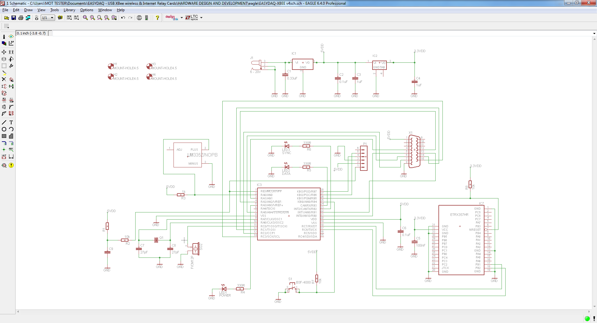

My circuit:


My new supply voltage requirement is +24V from +6V and I need a Vout of 5V to be supplied across the circuit. My max current is 0.4Amps. I can't utilise my LM7805 as the heat dissipation is just too much. See calculations based on the calculations below using help from this Power and Thermal Dissipation Tutorial by SparkFun - https://www.sparkfun.com/tutorials/217.

Power dissipation = V × I = (24V − 5V) × 0.4A = 19 × 0.4 = 7.6W

7.6W is too much heat.

Hence my question: which switching regulator (possibly available in the eagle libraries) would be suitable to take in a Vin of 24V or below and deliver a Vout of 5.0V?


Here's my schematic:

EDIT:

I've looked further into the use of the switching regulator specifically the LM2575-N to deal with the heat dissipation problem as outlined in my first post.

Please see my proposed approach below (Apologies if bits of the diagram are not that clear. I drew my approach by hand before committing time into finding the components in Cadsoft Eagle and subsequently updating my schematic).

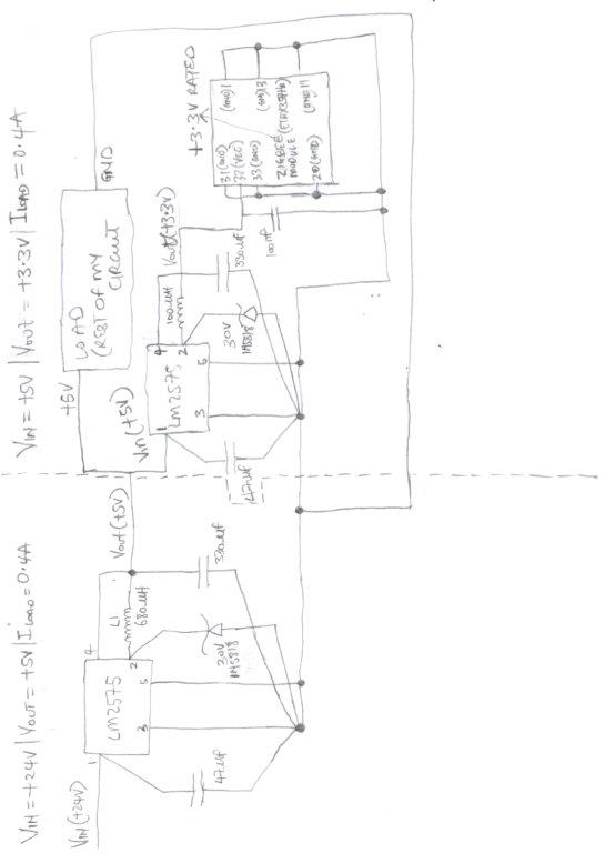
I also took the approach as seen here in order to supply +3.3V to the Zigbee module as seen in my schematic above.

The LM2575 on the LHS is for the stepping down of +24V to 5V and the Vout from this LM2575 is to supply +5V to the second LM2575 for stepping down to +3.3V which is supplied to the zigbee module. The +5V from the first LM2575 is also supplied to the rest of the circuit as seen in the circuit diagram above.

Does anyone foresee any problems with the approach e.g. with the selection of the input capacitor, inductor, output capacitor and catch diode? I came up with the approach by following the design procedure as per pages 12, 13, 14 and 16 of the LM2575 datasheet.

Any help is appreciated. Thanks.

  • Hi Alex,

    Thank you for the excellent question! Right of the bat, I applaud your decision to move to a switcher from Linear. The efficiencies and thermals are indeed magnitudes better however if EMI is a concern for your end application, please optimize layout and component selection to keep critical loops small and use shielded inductors.

    I've attached a presentation to help you optimize for EMI and Thermals. 0447.EMI and thermals Identify Critical Path.pptx

    As far as your layout and schematic is concerned, we have the perfect tool to help you get the right components, right IC, layout and schematic all in one tool. It's called Webench and you can access this on the front page of TI.com. 

    Put in your Vin, Vout and Iout requirements and webench will give you best price, total solution cost, number of components, design simulations for a variety of passives, design tips and reporting tools for formal discussions.

    I hope this helps in validating your circuit. Let me know if you need any further assistance.

    Thanks,

    Anston

  • Hi Anston,

    Thanks for the detailed reply. I'll look to optimising the layout and the component selection to deal with EMI.

    I'm also looking to having a Cout capacitor with LOW ESR as per advised by page 13 the LM2575 datasheet.

    In addition I intend on having low inductor saturation with the selection of the inductor.

    I'll look at taking the above into consideration when using the Webench tool.

    Apologies if this sounds basic but in my first attempt in using the Webench tool it initially asks for selection of a power supply solution which confused me slightly. For my final design i intend on using a regular +24v PSU with a 2mm connector and for my breadboard setup I'm using a Skytronic adjustable DC power supply.

    I went ahead and selected the 1st option - module/low EMI/easiest to use. I'lkl use the webbench tool with this and get back after utilsing it.

    NOTE: The powerpoint presentation seems corrupted when I open it. i attempted repairing it but to no success. Any other way you could get it to me?

    Regards,

    Alex.

  • Hi Alex,

    The three options that webench provides are the following:

    a) Modules - which have 2-3 passives and the inductor molded in along with the IC. Making for a very simple and straightforward solution with as few as 5-6 passives.

    b) Regulator - which is only the IC including power FET's but all passives need to be externally provided and connected.

    c) Controller - which is the IC without power FET's. That means, the FET's need to be provided externally as well along with other passives.

    For you I would recommend Modules and if your application doesn't bring up any modules use regulators. Avoid controllers as a first time design because it can get a little intimidating if you don't have the luxury of time to figure out what's going on.

    The ppt was for Office 2010, which might be the reason it appears corrupted. I've uploaded it again here: 7183.EMI and thermals Identify Critical Path.ppt

    Thanks,

    Anston

  • Hi Anston,

    Cheers for the answer. Let me give the web bench try now I know the difference between the module, regulator and controller options.

    I'll also check if the PPT can open

    Regards,

    Alex.