This thread has been locked.

If you have a related question, please click the "Ask a related question" button in the top right corner. The newly created question will be automatically linked to this question.

TPS6507x Power Path

Other Parts Discussed in Thread: TPS65073, TPS650732, TPS40200, TPS65070, TPS65950, DM3730

Question :

The TPS6507x datasheet does not explain the operation of the Power Path in detail.

Can you please explain how the Power Path is regulating the Charge Current voltage under der following conditions below?

Case 1:  USB (or AC) input present and Battery is not

 Case 2:  USB (or AC) input present, Battery is present and fully charged

 Case 3:  USB input present, Battery is present and is not fully charged and SYS load requires less than 500mA (example for this case 300mA)

 Case 4:  USB input is present, Battery is present and is not fully charged and SYS load requires more than 500mA (example for this case 800mA). 

             This is calledSupplement mode.

Case 5: USB is present, Battery is present and is not fully charged and combined SYS load and battery charge current require more current than the USB

            source can supply but less current than the USB switch is programmed to deliver.  This is DPPM mode.  As an example, use the following

            conditions prior to entering DPPM mode.  Assume the USB is limited to 500mA, the TPS65073 USB switch is programmed to deliver

            up to 1000mA, and the load requires 200mA, and the battery charging current is 200mA

  • Answer :

    The TPS6507x does have a Dynamic Power Path Management  (DPPM)  loop that is actively regulating the charge current based on SYS voltage.

    The DPPM thershold voltage can be adjusted ny User Register.

    For detailed inform,ation on DPPM, please check the following applicatio note http://focus.ti.com/general/docs/litabsmultiplefilelist.tsp?literatureNumber=slua400

    Case 1:  USB (or AC) input present and Battery is not

    ·         VSYS = USB (or AC) voltage.

    ·         USB switch is on, BAT switch is off

    ·         Maximum Load current delivered from SYS is set by either the USB or AC programmed maximum current.


    Case 2:  USB (or AC) input present, Battery is present and fully charged

    ·         VSYS = USB (or AC) voltage

    ·         USB (and/or AC) switch is on, Bat switch is off à no current form USB (or AC) pin is used to charge battery and battery is not supplying current to SYS

    ·         All of the current supplied by USB (or AC) input is feeding through to SYS load.


    Case 3:  USB input present, Battery is present and is not fully charged and SYS load requires less than 500mA (example for this case 300mA)

    ·         VSYS = USB voltage

    ·         USB switch is on and delivers 300 mA to SYS load.  BAT switch is on and USB supplies 200mA charge current to battery.


    Case 4:  USB input is present, Battery is present and is not fully charged and SYS load requires more than 500mA (example for this case 800mA).  This is called Supplement mode.

    ·         VSYS = Battery voltage because USB switch will be current limited.

    ·         USB and BAT switch are both on

    ·         USB input provides 500mA load to SYS, and battery will supply 300mA

    ·         USB switch is current limited and drops the USB voltage down to the battery voltage


    Case 5: USB is present, Battery is present and is not fully charged and combined SYS load and battery charge current require more current than the USB source can supply but less current than the USB switch is programmed to deliver.  This is DPPM mode.  As an example, use the following conditions prior to entering DPPM mode.  Assume the USB is limited to 500mA, the TPS65073 USB switch is programmed to deliver up to 1000mA, and the load requires 200mA, and the battery charging current is 200mA

    ·         With above conditions, SYS = USB voltage.

    ·         If the system current increases to 400mA, the USB source voltage will be in overcurrent condition and the SYS voltage will drop.

    ·         SYS drops to the DPPM Voltage as programmed by I2C.  See DPPM Loop section of electrical characteristics table in datasheet for available voltages.  The battery charge current drops to 100mA.

    ·         USB and BAT switch are both turned on.

    ·         USB input provides all the current it can provide will still maintaining a voltage equal to DPPM voltage.


  • Christian,

    I realize that this is an old post, but...

    What about Case X:

    AC is present and battery is not fully charged.  Does the charger automatically switch on and charge the battery with I(chrg)?  [I(chrg)=1000/R].  I assume this is the case but I don't see that happening.  

    If the battery is running the board (at 1.5A or so) and I plug in AC power, the battery current should reverse (charging the battery), correct?


    thanks,

    dave


  • When you are powering with the battery and you plug in AC power, assuming you are not exceeding any current thresholds and are not in DPPM or supplemental mode, the battery should stop supplying current and start the charge cycle.  

  • I do not believe I am exceeding any thresholds.  My battery has drained to 2.85V--is that below V(LOW)?  I thought it was supposed to continuously check for a battery at some point.  Either way, it's  still not working.  

  • How much current is your battery supplying before you connect AC?

    How much current is your battery supplying after you connect AC? 

    How much current is your supply connected to AC providing?

    Do you have the default register settings?

    Please post the schemtaic as an attachment.

  • 3426.bat charger.pdf

    Before I connect AC the battery is supplying 1.3A.  After I connect AC it drops to 0.  My 12V AC supply is sourcing .31A.  I do not have the register settings handy, unfortunately.  Our software engineer claims the battery charging register is set to the default values, which I believe enables the battery charger.  

  • With a 12 V supply connected to VIN, the TPS6507x will be in an overvoltage lockout condition. 

    Though the AC pin is specified to handle up to 17 V max, it is designed to operate at a maximum of 5.8 V. The high voltage spec is to tolerate spikes from an AC adapter. 

  • 6663.Register_settings_tps650732.docx


    I apologize, but I misspoke regarding the voltage.  My lab power supply was providing 12V, BUT, per my schemo I attached earlier I have 5V going into AC of the PMIC.  Attached are the register settings being loaded into the TPS650732 (in decimal format).  I have asked my software eng to provide real-time monitoring of the CHARGER ACTIVE register at CHGCONFIG3 - BIT 1.  

    After seeing these register settings can you comment further?

  • CHGCONFIG0 = 1 indicates that you are getting a battery temperature error. What thermistor are you using? Based on CHGCONFIG1 = 0h31 you have it set up for a 100k thermistor. Is this correct? Please post your schematic as an attachment, not inline with the post. 

  • We are not currently using a thermistor with our battery pack.  Perhaps that is the issue.  I appreciate the help.  The file should be attached.  

    bat charger_080111.pdf
  • You should be able to either change R274 to 100k Ohms or change CHGCONFIG1[4] to 0.

  • I left CHGCONFIG1[4] at 1 and installed a 10k resistor.  The charger began working at that point.  Now onto more testing.  Thanks!  

  • Now that I got the battery charger to function, it's time to get it functioning correctly.  I'd like to achieve a charge current of 1.3A.  My R(iset) = 768ohms.  If my battery is at 3.5V and I plug it into my up-and-running DUT I would expect to get a charge current of 1.3A until my battery reaches V(bat reg) = 4.2V.  But it is only 700mA at first.  An hour later when V(bat) = 3.75V, charge current is down to 500mA.  

    The datasheet states that the battery fast charge current is K(iset)/R(iset) when, among other things, there is NO load on SYS.  What exactly does that mean?  My DUT has an LCD it's powering which draws roughly 400mA.  

    Am I missing something?


  • Could there be an issue with my battery pack?  I am using pack of (4) 3.7V Li-ION batteries in parallel.  

  • Dave,

    Can you program bit 1 and 0 of register 0x01 to be 4F?  And let me know if you are still seeing the charge current limitation?

    -Jason

  • Jason,

    We just tried that without success.  But I didn't expect anything to happen since we are powering the unit thru AC.  I've been noticing that as the battery voltage slowly goes up, the current slowly goes down.  I thought it was supposed to stay at I(CHG) = 1.3A until the battery reached V(BATREG) = 4.2V.  At this rate my battery might make it to 4.2V sometime later in August.  :)  

    Dave

  • Since your battery voltage is > Vlowv (>2.9V in your case (default) with CHGCONFIG2[6]=1 binary), the charger should be at the fast charge current limit. 

    DPPM will reduce the charge current if VSYS is not at or above 4.5V (due to CHGCONFIG3[6:5]=11 binary (default));

    Also note, Kiset for an Ichg of 1.3A will be closer to 900 A*Ohms resulting in an Ichg of 1.17 A with Riset of 768 Ohms. 

    The drop across the power path might be close to 300mV at a load of ~2A which would attribute a lower voltage (maybe as low as 4.5 V?) on SYS and therefore throttle the charge current. Measure the voltage on VSYS to verify. 

    The note about fast charge current and no load on SYS means the fast charge current will only be achieved if the load + charge current is less than the AC pin current limit of 2.5A by default. As you reach this current limit, the SYS voltage will start to fall and the charge current will be reduced as I mentioned above

    Have you verified that your TPS40200 is regulating and capable of supplying the 1.7 A (1.3A (Ichg) + 400mA (load))?

    Also, you coud try clearing WLED_CTRL1[7] to see if removing the LCD load will allow you to reach the fast charge current limit. 


  • Some notes on your recent comments:

    VSYS is at ~4.9V.  

    The TPS40200 is regulated nicely and it is designed to provide up to 3A.  

    As far as WLED_CTRL is concerned, bit 7 is already a zero.  We do not use the PMIC to power this particular display.  We use an on board boost regulator to provide 5V (from 3.3).  

    Good news:  I tried a 2nd, identical, battery pack today on the charger.  Before I hooked it up the pack had a voltage at 3.15V (3.7 nominal).  Upon hooking the battery up there the charger began supplying 1.2A, which is what I was expecting all along.  

    BUT, according to the datasheet the charge current should stay constant until the battery voltage reaches V(BAT REG) = 4.2V.  Please see attached to observe the charge current vs battery voltage data.  

    battery charger_data.xls
  • Indeed the charge current should be constant at Imax until Vbat gets to 4.2V.
    One thing that would alter this is POWER PATH management.

    I suggest you measure the input current from the AC source into the TPS65xxxx while monitoring charge current.
    Monitoring input current and charge current would tell us if current is going out to the DCDC loads.

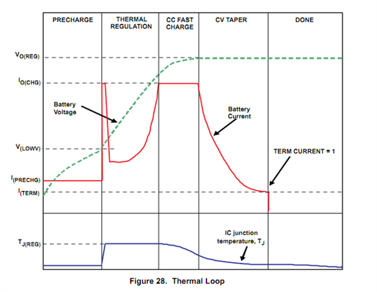
    The other thing that would affect charge current is THERMAL REGULATION. (previous post shows this graphically)
    This is a linear charger, so it will develop heat.
    Heat power dissipated = [Vin (VAC) - Vbat ] x Icharge.
    5V at VAC - 3.3Vbat = 1.7V,  at 1.2Amps the power dissipated is 2Watts.
    2Watts is a lot of heat in that package.
    Since the charge current slowly drops it leads me to believe the IC is heating up and going into thermal regulation.

    NOTE: the power pad must be soldered to a good copper plane for thermal relief as the data sheet shows.

  • Dave,

    Has your issue been resolved with this charger on the PMIC?  I wanted to know what issues you were still having.

    -Jason

  • Jason,

    So far so good.  Ed Walker's comments were spot on.  I was attempting to push too much current through the PMIC.  At this point, I believe the charger is working correctly.  Thanks.

    dave

  • I think I spoke too soon.  The battery charger is operating at 500mA or so and charging my battery up to 4.0V.  However, FULL charge on my battery is 4.2V.  The register setting at CHGCONFIG2 bits 5 and 4 is set to "10" = 4.2v.  

  • What happens after the battery reaches 4.0V? Does it stop charging? Reduce charge current (if so, to what)? Can you provide oscilloscope shots?

    The reasons (other than full-charge, chg disabled, etc.) charge current may be reduced are noted in the datasheet and in the following design note: http://e2e.ti.com/support/power_management/pmu/w/design_notes/tps65070-low-charge-current.aspx


  • I made a small gaffe in my previous post.  I originally had my Riset at 768ohms to achieve a charge current of 1.2Amps.  When I had this setup, I was getting an initial charge current of 700mA @ Vbat = 3.15v.  However, after about 8 hours, charge current went down to 250mA @ Vbat = 4.0v.  

    I then changed my Riset to 2k to lower the charge current and to avoid thermal shutdown.  

    In this scenario, my initial Vbat = 3.4v, charge current started at 450mA and remained steady for several hours.  The battery charger turned off (I was monitoring the reg settings) @ Vbat = 3.80v and charge current = 450mA.  

    I used this charging scheme several times with the same results.  The charger just seems to shut off.  I do not see the thermal shutdown register being flagged.  I know that my AC adaptor can supply plenty of current but I have not been monitoring Vsys.  


  • Dave, 

    Did you have any developments with this? 

    I still only see thermal, current limit (TPS65070 or upstream), or VSYS as limitations on the charge current. 

    Can you perhaps confirm this behavior with an evaluation module,  a known good configuration?

    Thanks, 


    Daniel

  • Daniel,

    It was definitely thermal shutdown.  The one thing I never got working is the battery charge voltage.  My battery one got up to 4.0v before the charger shutdown--I was looking for 4.2v.  My register settings were def set to 4.2v.  

    I have been off this project for a couple of weeks now.  I am now working on a DM3730 design using the TPS65950 PMIC, so more fun in store!  

    I appreciate your help, Daniel. 

    Dave