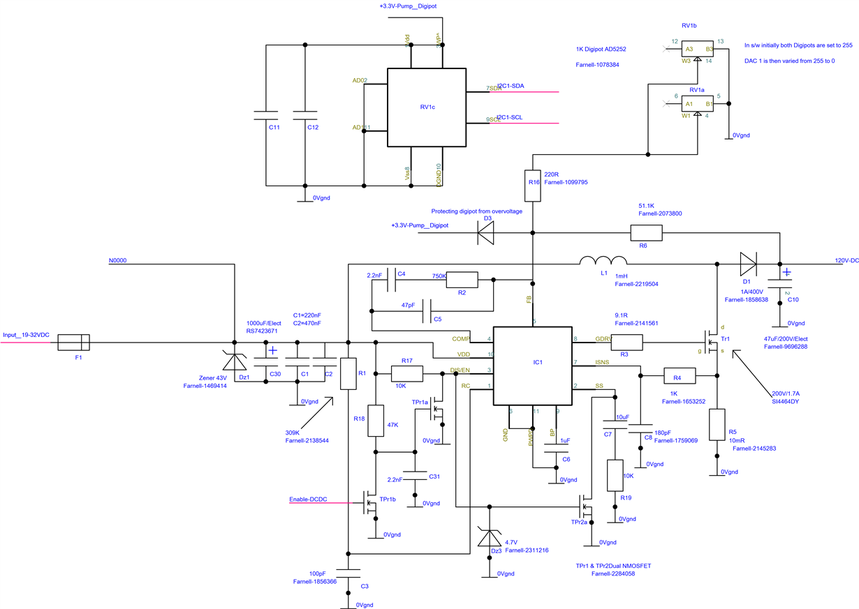
I have build a circuit using TPS40210 Boost converter from TI. The circuit specs are:
Vin = 19VDC to 32VDC (Could be any DC level in between these limits)
Vout = 48VDC to 120VDC (Variable output voltage obtained by varying DigiPOT value in feedback path) (Max Load current is 100mA)
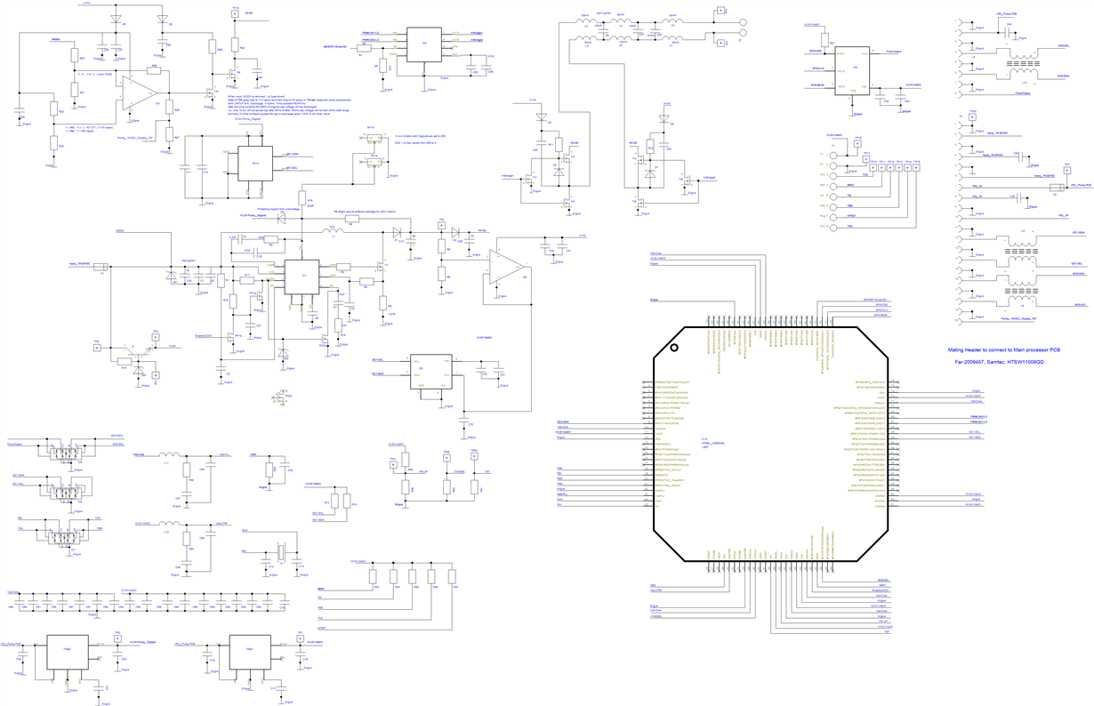
The circuit is as shown in the attached picture (This is the circuit of DC-DC converter side only). There is other circuitry on the same board that contains processor and also downstream DC-AC conversion circuitry using PWM from processor. But, the problem I am facing currently is there even when I isolate the DC-AC conversion circuitry
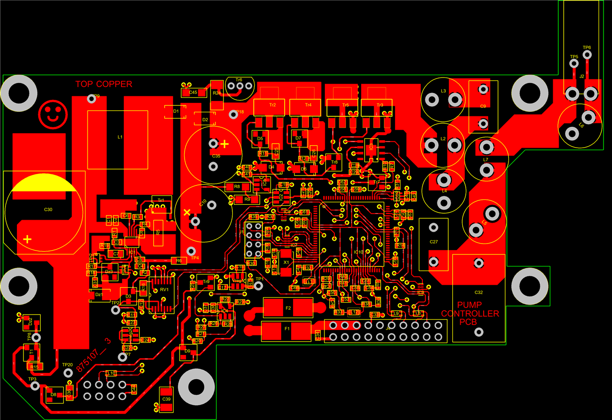
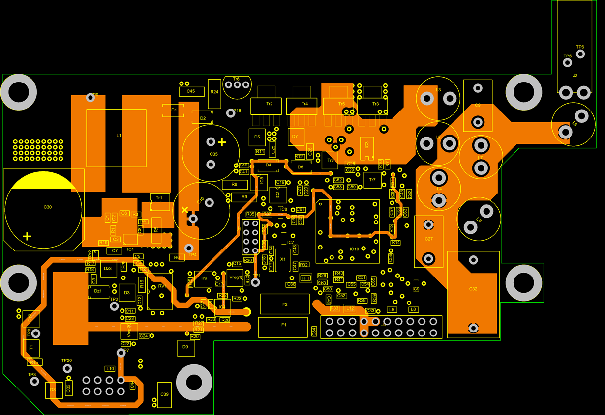
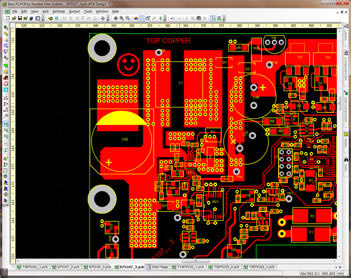
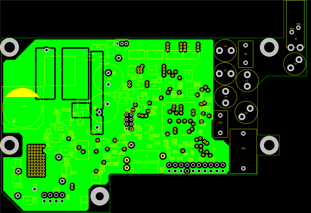
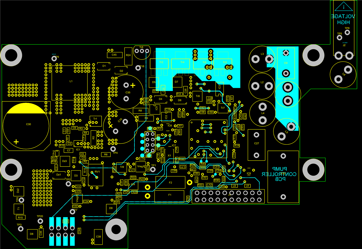
I have also attached the layout of the PCB
This is a 4 layer PCB with 1oz Cu
I have tried to copy the layout from EVM module as much as I could.
Processor changes the Digipot values in steps to vary the output coltage from 48V to 120V apprx
This circuit has been working fine previously on about 20 different PCBs.
We have just ordered some more of these PCBs, and all of sudden this circuit became too noisy
To start with it induced a noise on processor Reset line causing it to go in reset state randomly. that never happened before I managed to get around that by putting a10nF cap on processor Reset line.
So, processor is now working but DC DC converter keeps going to shut down mode when Digipot changes from value of 30 downwards corresponding to 70V apprx upwards.
In previous PCBs it worked fine when Digipot was changed from 255 down to 0 in steps of 10 and DC DC converter never went to shut down mode BUT
In these PCBs, it started to go down to shut down mode. I tried few changes as:
I changed the step size from 10 to 2 (used 5 before and sometimes it worked fine for few cycles but at other times, it went to shut down mode). Couple of PCBs worked fine at this step size (although they were still noisier and had to use cap on Reset line). All other PCBs are still problematic as in DC DC converter keeps going to shut down mode.
I also tried disconnecting DigiPOT and connected an external analog POT and found that it changing the POT abruptly caused the unit to go in shut down mode so decided to use the smaller step size
Changed inductor, 10mR current feedback resistor, TPS40210, current sense cap from 180pF to 47pF (but problem is still there)
The output of this circuit is also monitored by using potential divider, buffer and ADC (i2c – comms with ADC )
Our s/w engineer has helped me in modifying the software for the processor, that if it ever detects less than <40V then it Disables the converter (Enable-DCDC line shown in the schematic) and enables it again. This helps for quick discharge of 10uF cap connected to ‘Soft Start’ pin as shown in the diagram. But problem is still there and sometimes it works and other times it keeps collapsing even when it is sitting at one voltage level (usually 70V upwards i.e., anything from 70V to 120V). It collapses, goes to disable mode and then enables again (done by processor for faster response to avoid the wait time until soft start cap discharges)
There is a series resistor of 220R (R16) connected in feedback that limits the maximum voltage that could be obtained when digipot is sitting at 0
The component values are indicated on the schematic. I designed this circuit originally by using Webench from TI and also with the kind help of TI sales rep from Arrow electronics who helped us in obtaining EVM modules for this converter. As I said this circuit has been working fine before but all of sudden it decided to have a tantrum. Please help
PCB is 4 layer, see attached pictures indicating each layer
Also, there is a picture showing the plated through hole vias used on DC DC converter side connecting the copper areas on all 3 layers


