This thread has been locked.

If you have a related question, please click the "Ask a related question" button in the top right corner. The newly created question will be automatically linked to this question.

TPS60311 inquiry

Other Parts Discussed in Thread: TPS60311, TPS610985, TPS61098

Hello,

I have a customer who is designing a sensor with energy harvesting.

For powering sensor, he choose TPS60311 because the required power is so small and charge pump IC can save space.

But  there is a problem and we need help.

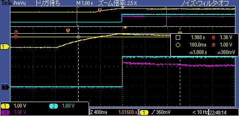
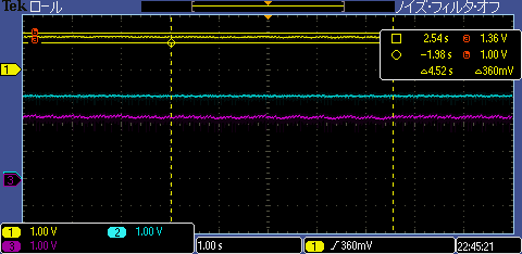
Please see attached file for the detail and give us your comment ! 

Thanks and besr regards,

Hiro

TPS60311inquiry20150820.pptx

  • Without waveforms, your issue is not clear. But it sounds like the TPS60311 does not start up when powered from your energy harvester? The charge pump likely requires more energy at startup than the harvester can provide. Such is usually the case with older devices such as this charge pump.

    More Cin would be one possible option to investigate in order to store enough energy to start the IC. Try 100uF and see if it improves.

    But would a device like TPS610985 be much better for the application anyways? The 55 uA Iq of the TPS60311 seems quite high for a source which can only provide some uA itself.
  • Hello Chris-san,

    Thank you for your quick replying and your information is very helpful.

    I'll ask the customer to send waveforms and tell them your comment.

    By the way, is TPS610985  a brand-new preview device or some spin of TPS61098 ?

    I could not find any TPS610985 information from TI web and ESP. 

    Thanks and best regards,

    Hiro

  • Hi Hiroshi-san,

    TPS610985 is a metal spin of TPS61098 and it's still in development, so the information is limited on web. The main difference is shown in the datasheet and other parameters are same with TPS61098, such as quiescent current.

    What information are customer interested in?

    BR

    Gene

  • Hello Gene-san,

    Thank you for your information,
    And all functions and parameters of TPS610985 is described in TPS61098 datasheet , right?
    Then, I'll send them the datasheet.

    Thanks,
    Hiro
  • Hello Chris-san,

    I have got  two waveform, but that are with changed capacitors values and seems work good.

    (due to changing parts and  preparing test equipment, the waveform with inrush current will be available next week)

    So, today' questions from the customer are as below,

    - Are these values reasonable  for their application ?

    - Is there any calculation formula for Cin, C1F,C2F values ?

    the changed values:

    Cin=470uF, C1F=C2F=0.47uF

    the colors of the waveform:

    Vin=yellow, Vout1=purple, Vout2=light blue

    Thanks and best regards,

    Hiro

  • Yes, providing energy from a current limited source usually requires a larger capacitor as you have on the front end. I would recommend making the other 5 capacitors around the TPS60311 be the D/S recommended 1 uF value. For sure, the IC requires a 1uF right next to its pins after the switch shown in your drawing.
  • Hello Chris-san,

    Thank you for your comment, I understand.

    The customer really want to know is the method to optimize capacitor value  by themselves,

    so,  formula and Spice model are asked. Could you answer this question ?

    Thanks and best regards,

    Hiro

  • We don't have a model for this very old device.

    There is no precise formula. They will need to test it empirically in their system. As well, I assume the output characteristics of their source have no formula.

    Basically, you need to store enough energy in the input cap to power the load and charge up the output caps.
  • Hello chris-san,

    Thank your for your quick replying and your comment.
    I'll talk to the customer and basically they need to test it empirically for optimizing these capacitor value.

    Thanks and best regards,
    Hiro