I tried the SimpleBLEPeripheral example program in TI BLE1.4.0 stack. I change the P0_7 to P1_5 because I use P1_5 in my board.
In all the following experiments, HCI_EXT_MapPmIoPortCmd( HCI_EXT_PM_IO_PORT_P1, HCI_EXT_PM_IO_PORT_PIN5 ); is always disable, and I force P1_5=1; before osal_start_system(); which keeps TPS62730 always in DCDC mode.
And I am pretty sure the ON/Bypass is always 1 during the experiments.
1. With POWER_SAVING enable.
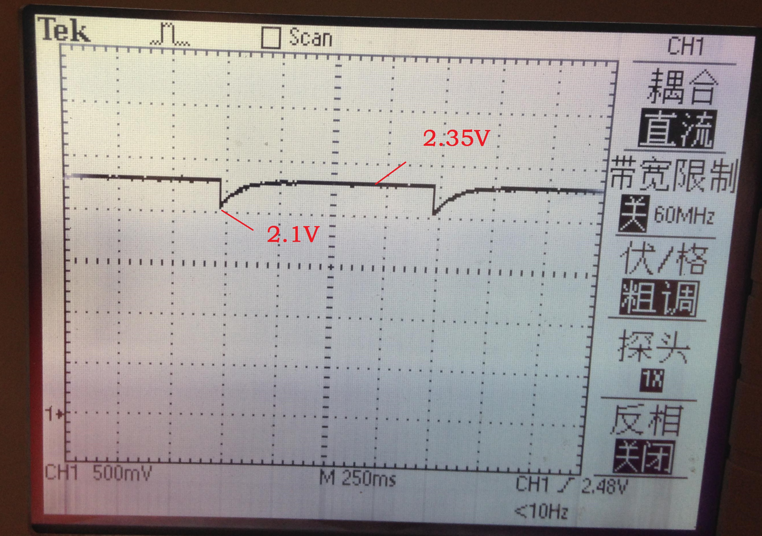
The Vout of TPS62730 should be stable 2.1V. But I get the following waveform.
The Vin of TPS62730 is 3V, which is connect to a TEK power supply.
The time interval is 1s, which is the ADVERTISING_INTERVAL.
As can be seen in the figure, the Vout of TPS62730 rise to 2.35V when CC2541 goes to PM2 mode. That is quite strange.
2. With POWER_SAVING disable.
The Vout of TPS62730 is stable 2.1V.

3. In the case of 1, if I connect Vout of TPS62730 to the PIN2 of CC-debugger(PIN2 is connected to 74AVC245 VCCB pin). The waveform is 2.1V stable.
4. In the case of 1, if I delete this line "ADCCFG |= HAL_ADC_CHANNEL_5;" in my program, which is executed before P1_5=1. The waveform is 2.1V stable. I think maybe this change increase the Iout a little.
I think in 2,3,4 shows that, the problem may have some relationship with Iout of TPS62730 on my board. It seems when the Iout is too small, the Vout rises to 2.35V. So I tried the 8 experiment.
5. I disconnect the Vout of TPS62730 to the power net on my board, so that Iout is nearly 0. (P1_5 is still forced to 1) I suppose to see the Vout be unstable. But the result is: 2.1V Vout is stable.
6. I tried 3 boards, they have the same phenomenon.
I think there must be something wrong with my hardware. I've checked the schematic, I think the part of TPS62730 is the same as the KeyFob.
And I've checked the value of caps and inductances, they are all right.

According to the waveform in 4, does anybody have any idea on the cause of the problem?
Frank