This thread has been locked.

If you have a related question, please click the "Ask a related question" button in the top right corner. The newly created question will be automatically linked to this question.

UCC28070 Problem with input line variation

Other Parts Discussed in Thread: UCC28070

Hello,

we are testing a 3850W PFC module, with  UCC28070. During the tests we have seen that at full load if the input voltage goes down from 230V to 225V there is an input current raise  with an increase of the output voltage that some time it makes happen an overvoltage protection. I think it is related to the level change of the UCC28070 linear multiplier.

We have increase the output capacitors to 4x470uF, without solve the problem.

The output voltage is 390Vd so the Vsense and Vinac resistor are:

Rtop=3200k        Rbottom=24.9k

The    Rimo=47k

The voltage error compensation is:

Cpv=100nF+47nF     RZV=82k   CZV=1.5uF

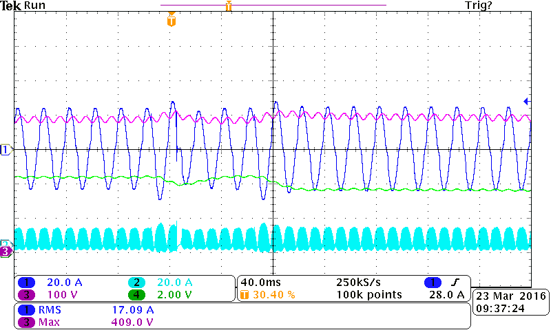
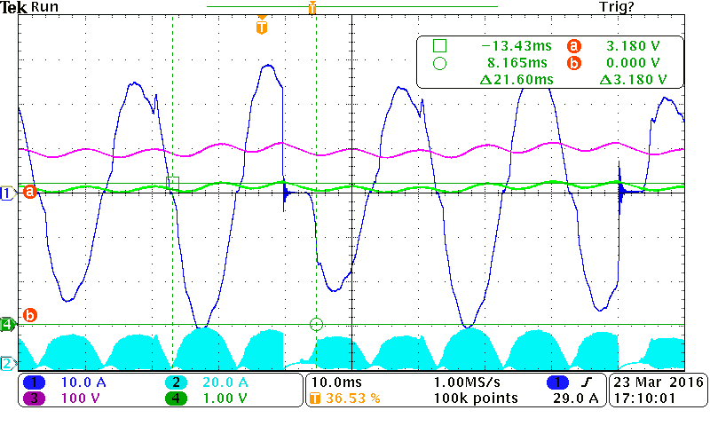
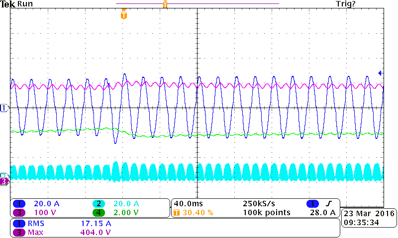
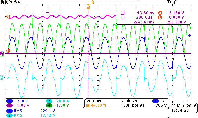
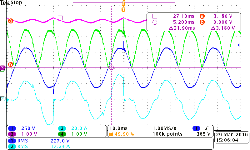
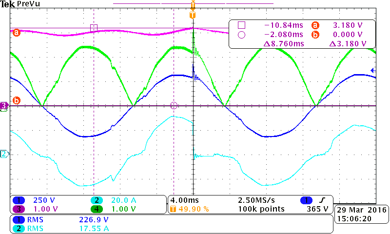
I enclose 2 pictures, the first with no problem the second with the problem.

Traces   1=input current   2=switch current   3=output voltage  4=VAO

No problem without stop input current

Problem with the stop input current

  • With the pfc output set at 390V, the OVP level has a nominal value of about 413V.
    I cant tell if you are getting this but it look like the pfc is shutting down so it may well be the result of an OVP condition.
    The input voltage is only changing from 230V to 225V.
    This is not going to be enough of a change to affect the multiplier output.
    The multiplier is a quantized type ( not linear) and with the values chosen , it will remain in the fixed state.
    which is level 7 of Table 1 in the data sheet.

    Do you have any filtering capacitor on VSENS and VINAC pins ?
    The problem occurs at full load which makes me wonder if the problem is related to the noise associated with switching at higher power
    Can you please monitor the voltage on VSENS and check that it reaches the OVP level (which is 3.18Vdc) ?

    John Griffin
  • Hello Jhon,

    thank you for your feedback.

    About the question in the pins VSENSE and VINAC  there is a capacitor of 2n2F in parallel to the bottom resistor 24k9.

    I enclose the picture where you can see that the VSENSE =3.18V  when it goes in protection (see "a").

    Traces    1=Input current   2=switch current   3=output voltage  4=VSENSE signal

    You can see that during the before cycle there is a pick in the input current, and the following half cycle the maxim value is increased.

    The phenomenon happens between 230Vac and 228Vac

    Tarcisio Pellencin

  • Hello Jhon,

    thank for your feedback.

    About the question in the pins VSENS and VINAC there is a capacitor of 2n2F in parallel to the bottom resistor 24k9.

    I enclose a picture where you can see the voltage on the VSENS when it happen the problem is 3.18V (see "a"). In particular

    during the cycle before the problem, you can see a pick in the input current, when it is going down and in the half cycle

    after the maximum value of the current raises.

    Traces    1=input current  2=switch current  3=output voltage  4=VSENS

    Tarcisio Pellencin

  • Do you have a schematic and BOM for the power supply?
    I notice that there is a significant current spike on every second cycle of the AC signal
    There may be some issue with the current loop. Perhaps the current transformer is not properly detecting the switch current.
    Or perhaps Rsynth is not set to the correct value.
  • When there is not the problem,  the current is symmetric, as you can see on the following pictures. The increase of the current near 120ms is related to an reduction of the input voltage without overvoltage protection.

    About the schematic and BOM, we are planning to make some tests next week then I will give you the results.

    Tarcisio Pellencin

  • Hello John,

    I make a brief summary.

    We are developing a PFC circuit for a devices that it can run in the input voltage range from 85Vac to 265Vac. The device monitors the input votage and changes the power that it can deliver, so in the low range (85Vac to 120Vac) the maximum deliver power is 1900W while in the high range (180Vac to 265Vac) the maximum deliver power is 3850W.

    We have used the “UCC28070 Controller Setup Tool” to design the PFC. Then we have tested the circuit at low input voltage with a 1900W load and we have adjust the Pklimit to the maximum input current. Next we have increased the input voltage on the high range (180 to 265Vac) and we have adjusted the RIMO to have nominal power of 3850W.

    The PFC works well with the input voltage fixed. However if at maximum load, we incresed the input voltage over the thershold of level 8 the PFC goes correctly but when the input voltage returns to the level 7 the amplitude of the input current increases and the PFC goes in overvoltage protection.

    The output voltage is 390V, the top resistor is 3200k and the bottom resistor is 24.9k, so the KR=0.0077.

    The threshold from level 7 to level 8 is:

    VIN peak=2.6/0.0077=338V, so the input threshold is Vth+= 239Vrms

    the threshold from level 8 to level 7 is 5% lower so the input threshold is Vth-= 227Vrms

    Below a problem we have seen when the input voltage has gone under level 8

    Traces:    1 input voltage    2: input current    3: VSENSE    4: VINAC

    As you can see on the picture, every time there is the problem, in the input current there is a little pick, during the decrease of the current. During the following half cycle the amplitude's current increases and so the Vout, then it goes in overvoltage protection.

    Next there are 2 picture with the time expanded

    I have enclosed the "UCC28070 Controller Setup Tool.pdf"

    UCC28070 Design 1900V 85_265V.pdf

    Tarcisio Pellencin

  • Hi Tarcisio,

    The document you attached shows your calculations are based on a 1900W load and your waveforms are  taken at 240Vrms where you say
    the load is 3850W. Not really sure what to make of that but you need to make the calculations at 3850W.

    The value of PKLMT sets an upper limit for  the peak of the sensed current. This occurs at max power and peak of input voltage.

    If you calculate this at a lower power and input voltage then the UCC28070 will trip off due because of sensing a peak overcurrent signal.

    I think that is what is happening with your waveforms. You are getting a large inductive spike when the gate drive is `switched off.

    Im not sure  why this is. It may be due to a poor layout. I recommend that you

    • calculate component values at max power
    • monitor the current sense inputs CSA, CSB
    • check layout of power supply.

    I hope this helps with your troubleshooting.

    If you need further help please provide a schematic with BOM and a pcb layout

    Regards,

    John

  • Hello John,

    thank you for your help.

    I will calculate the component at max power and monitor the CSA, CSB signal.

    I will give you a feedback.

    Regards,

    Tarcisio