A related question is a question created from another question. When the related question is created, it will be automatically linked to the original question.
If you have a related question, please click the "Ask a related question" button in the top right corner. The newly created question will be automatically linked to this question.
I don't believe we have designed with this transformer in the past for poe. However, if looking to design around this transformer, I recommend using the below link to design a very simple low cost flyback using this transformer's parameters. www.ti.com/.../slva305c.pdf
we need a low-profile design with 10-13W power and below 9mm height. Maybe you do have a reference design with a transformer on a EFD15 or similar low profile core?
Unfortunately, we currently do not in our poe designs. I recommend using the design guide above. Or talking to your local TI FAE to help with a custom power supply design.
thank you so much for pointing me to your design change, based on the slvua27a. My only concern is that you are limited to 9W of output power by using only 2 of the 3 secondary windings of the 749119350.
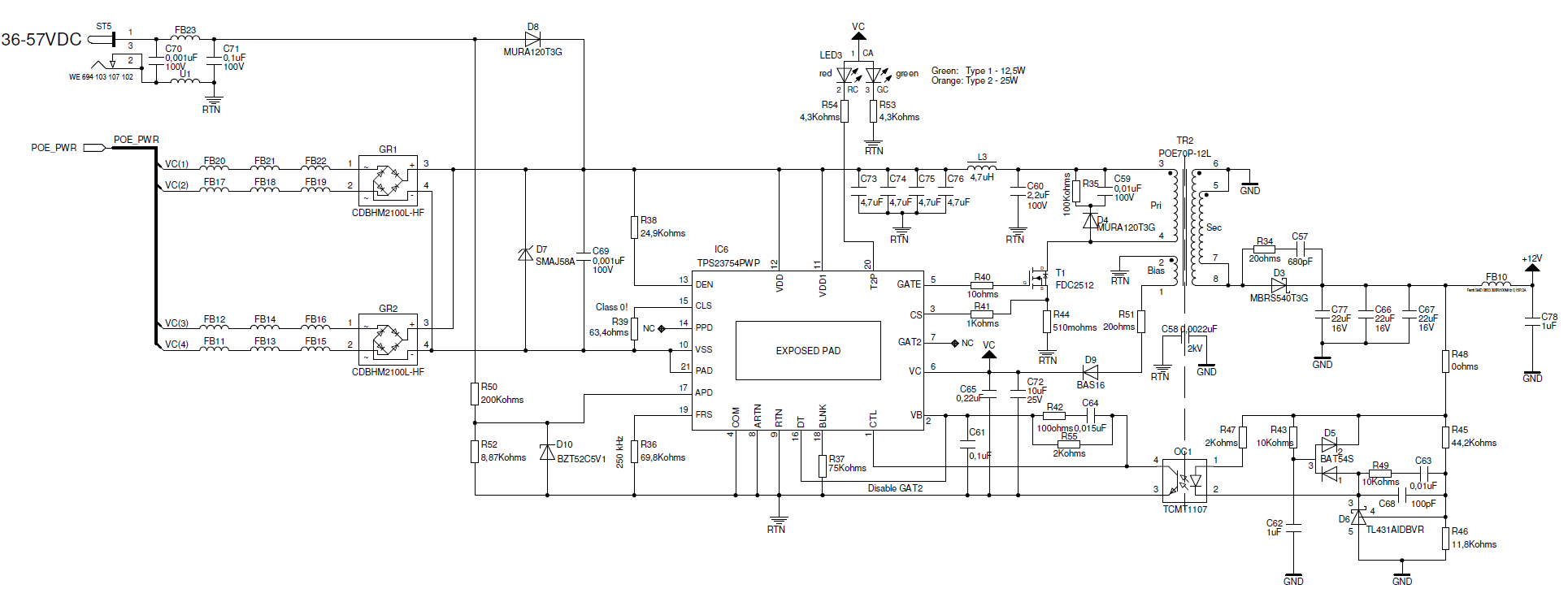
We have based our design on the low cost reference design slvrb20.pdf, replacing the Coilcraft POE13P-50L with the Würth 749119350. Of course there is no synchronous but a single Schottky diode rectifier, so efficiency will not be as good as in your design.
following your advice I have a functional TPS23753A low cost flyback design. Do you have a proposal for a TPS23754 low cost design?
I would need only 3W on the 3,3V output side but app. 20W on the 48-57V DC/DC input rail. Could I use the DC/DC flyback from the TPS23753A also on the TPS23754?
I don't see an issue with using the same power stage as your TPS23753A converter for the low power solution then having the TPS23754 take the rest of the power between VDD and RTN. You can even use the app note on the first post of this thread to calculate the solution for any of the parameters that might've changed.
What is your output current?
We have some reference design with dual output, but it's not a diode rectifiers design.
However, you can modify the schematic to meet your spec.
-Ben
Please click the Verify Answer button on this post if it answers your question. Thanks!
Hi Ben,
thanks for the reply. We have about 0.5 - 0.6 A of current.
Please not that the role of "output" or "input" is not fixed: Depending on where power is available, inputs and outputs might switch places.
--Michael
Sorry, I can't catch what you mean "inputs and outputs might switch places". Can you give me more detail about your block diagram for you application? It's will very useful for me to give a best solution for you.
I assume that you want to find 12@0.6A and 3.3V @0.6A, so we can modify reference design "PMP8454" to meet your spec.
sorry for not being clear. We have 2 boxes, one local and one remote, which are connected by a DC@48V 2-wire line. Usually the local box would feed 48V@0.6A to the remote box. The remote box has a bridge rectifier at the 2-wire input, in order to safeguard against wrong polarity of the 2-wire line. So the 2-wire line is polarity agnostic. In this case the local box provides the power output and the remote box the power input.
However, if there is no power at the local end available, we would like the option to reverse feed the local box from the remote box. In this case the power input and output are reversed and we have the task to go around the bridge rectifier for the reverse power direction. One idea was to use 2 hot-swap circuits and enable them for each direction.
Hi Ben,
sorry - I mixed up a different thread. Forget what I just wrote. Yes, we need a low cost design with 12V@0.1A and 3.3V@0.5 or a total of app. 3W. I believe at 3W power the synchronous rectification is not justified and we could use Schottky diodes instead.
--Michael
- SLVU314F (with components selected for 12V from the BOM)
- PMP6812
- PMP8803
The point is that component values differ a lot, and I am confused which of the above I should use. For example the feedback loop or the series resistor for current sensing are quite different in terms of resistor and capacitor values
Choose the right compensation value is based on your whole system.
For example, you used different transformer and had different inductance. so your compensation value should be different.
Choose one of above reference designs which is fittest your spec.