This thread has been locked.

If you have a related question, please click the "Ask a related question" button in the top right corner. The newly created question will be automatically linked to this question.

Issue with TPS92511

Other Parts Discussed in Thread: TPS92511, TPS61165

Hi,

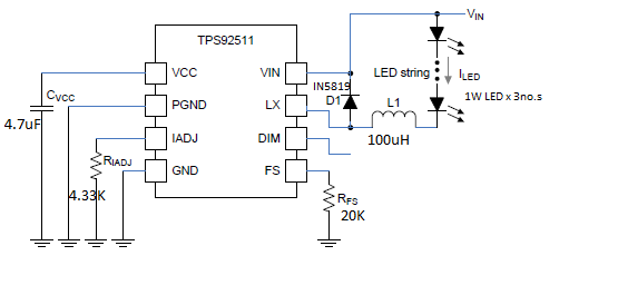
I have been using TPS92511 with following circuit configuration. It is supposed to drive the load of a single  1W LED with 350mA constant current at varying input voltage levels from 4.5V to 12V as per my requirement.

At input voltage of 4.5 V the LED is driven by 350mA and 3.2V drop across the LED, but as the input voltage is increased further to 5V and 6V the current is not remaining constant at 350mA. It increases to 450mA, 600mA respectively.

Kindly suggest me to improve the circuit configuration to attain constant 350mA  to drive single LED from a Li-ion battery source.

  • Often times regulation issues are noise related and can be from poor layout, improper bypassing, or both. Are you testing this with the TI EVM or your own PCB? Are you breadboarding it by chance? I also don't see an input capacitor in your schematic. Are you using one? What inductor part number are you using? If you are not using the EVM I would be happy to look over your layout for issues.
  • Hi Clinton,

    Thanks for the prompt reply.

    We have designed the PCB and are using the same for testing.

    Please find the PCB layout as shown in the figure below and suggest modifications to the same if any.


    The inductor value is 221 smd inductor ie 220uF

    Yes, we have included the input capacitor of value 47uF,63V. Please suggest whether any higher value is to be included.

    What will be the function of the capacitor at the input side?

    We hav also provided a 2V supply to the DIM pin i.e 6th to enable its dim function, inorder to see any variation in performance , but could not find any improvement

    I look forward to hearing from you soon.

    Thanks,

    Mehul.

  • Correction: Inductor is 221 uH and the capacitor is 4.7 uF.
  • The layout looks ok as far as placement goes, but I'm not sure about the grounding. Do you have a backside ground plane? All the forward currents through the inductor and diode will need a return path to the input capacitor and IC grounds. If you have a ground plane that should be ok, if not that could be your issue as it will generate a lot of noise. Also of concern is the IC thermal pad. I don't see a pad for it on the board. Do you have one? Is it soldered down correctly? If that pad is not connected directly to the ground pin beneath the device you could have noise issues as well.
  • Hi Clinton,

    It seems there were issues with the PCB tracks etching. We have ensured that there are no shorts between the tracks and the circuit is working now!

    ---------------------------------------------------------------------------------------------------------------------------------------------------------------

    We are also working to develop a boost driver based on TPS61165 and have posted our query here.

    We have also checked the track issues in this PCB, but still we are not getting the desired results.

    The output voltage was being boosted (without load), but when we connect a 3 LED in series load, the output voltage drops.

    It will be really nice if you can help with this IC as well.

    I look forward to hearing from you.

    Thanks,

    Mehul.


  • I'm not familiar with the IC, but I will try and find the correct contact for you and pass this along. I'm glad you debugged the other problem.