- Ask a related questionWhat is a related question?A related question is a question created from another question. When the related question is created, it will be automatically linked to the original question.

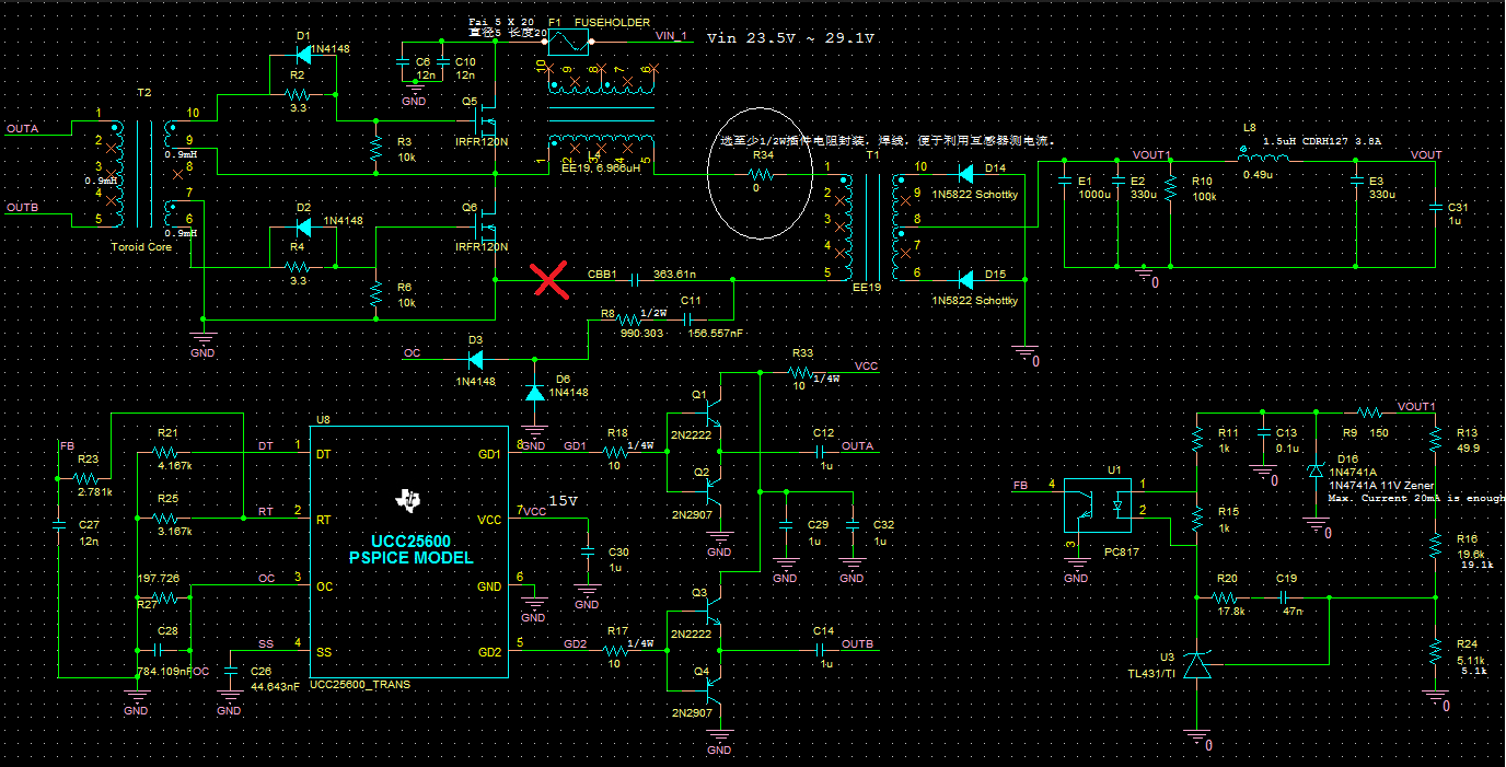
Sch is as follows
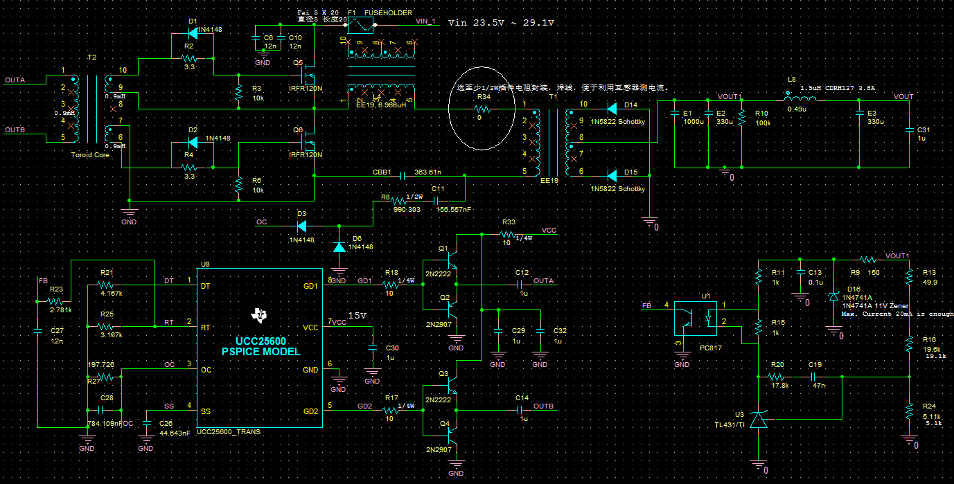
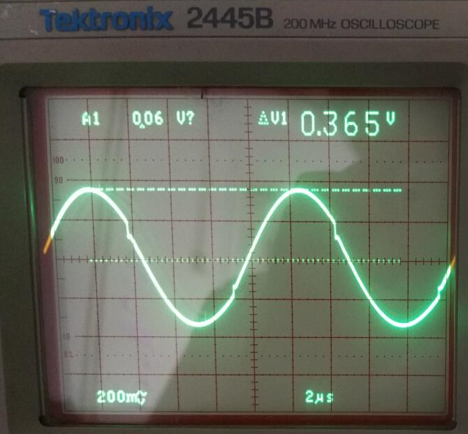
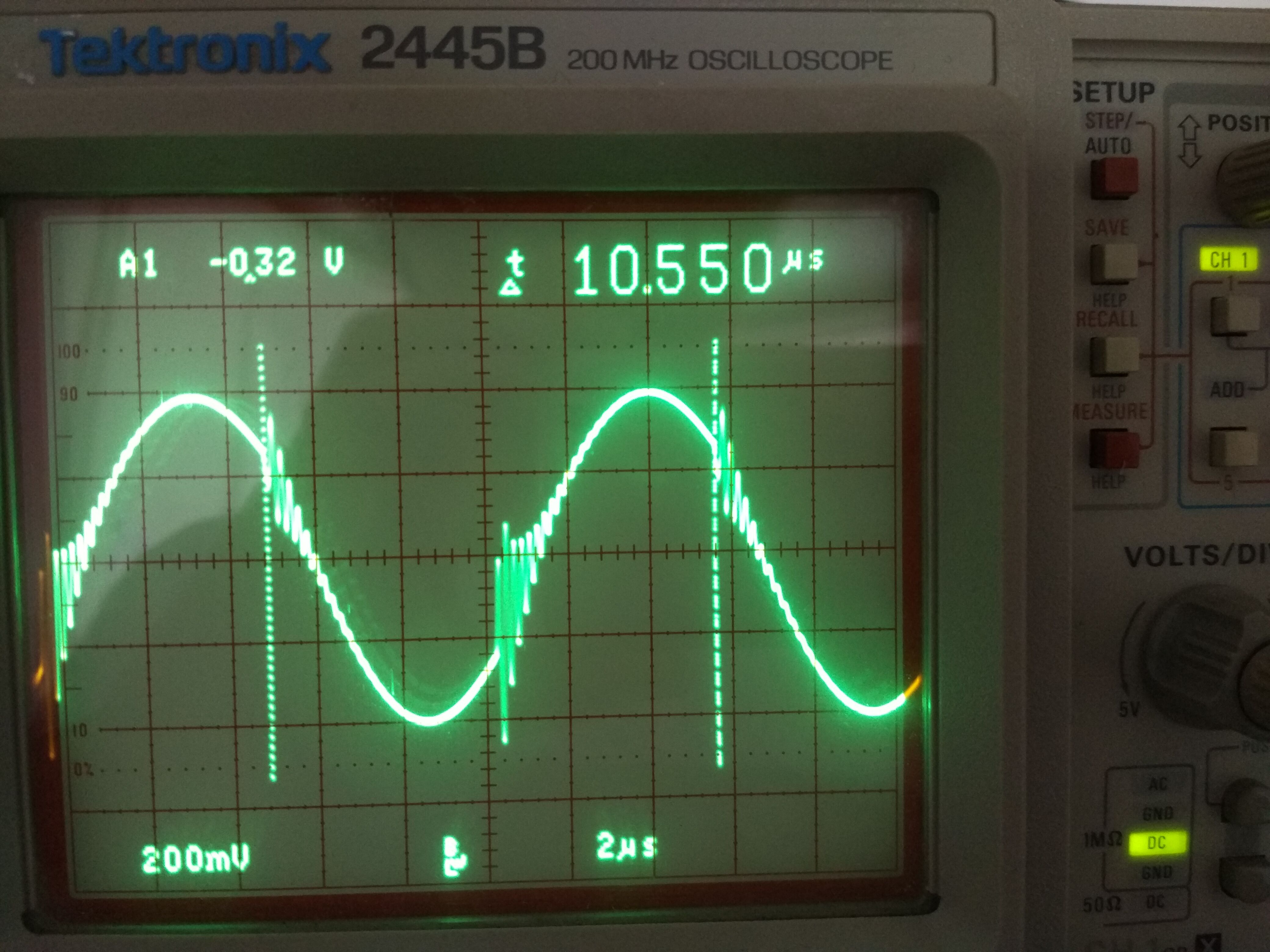
Test result is as follows ( adding a series resistor in the resonant network, and test this resistor's voltage. R34 in the sch is this series resistor, with the value of 0.2R )
Note:First waveform is the voltage across R34.
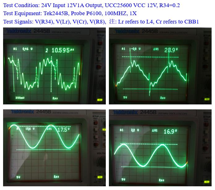
We can see that the resonant current(voltage across R34) is very strange, is there someone else having the same experience?
And could somebody tell me why?
But if i use the Current Transformer made by myself using a ferrite toroid core, test result is as usual.