This thread has been locked.

If you have a related question, please click the "Ask a related question" button in the top right corner. The newly created question will be automatically linked to this question.

[ LMG3410 ] Optimal Dead Time

Other Parts Discussed in Thread: LMG34XX-BB-EVM, LMG5200, ISO7831, LMG3410-HB-EVM

[ LMG3410 ] Optimal Dead Time

Hi,

Can you help me to understand the optimal dead time for half-bridge with LMG3410?
As my understanding, the too long dead time would cause power loss. On the other hand, of course, we need to prevent on-on state and shoot-through with appropriate dead time between two LMG3410s.

<Q1>:
Do you have any guide lines how to calculate valid dead time for half bridge with LMG3410?

I checked the user's guide of LMG34XX-BB-EVM, 50nS dead time interval is set. This dead time is applicable for switching frequency between 50KHz and 200KHz. Correct?
My customer's Fs is around 8KHz, in this case, any recommendation and/or limitation of dead time?
The current dead time which customer set is around 2uS.

<Q2>:
The LMG3410 datasheet says that...

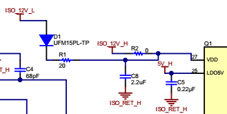
"If a large deadtime is needed, a 14-V zener diode can be used in parallel with
the VDD bypass capacitor to prevent damaging the high-side LMG3410."

How can I know my dead time is large or small?

Thanks,
Ken

Reference

Deadtime Effect on GaN-Based Synchronous Boost Converter and Analytical Model for Optimal Deadtime Selection
ieeexplore.ieee.org/.../login.jsp

LMG5200 Simulation Dead Time V.S. Power Loss
e2e.ti.com/.../410260

  • Hi, Ken

    Thank you for your questions and interest in LMG3410.

    Q1:

    Answer: In most cases, we want reduce the deadtime as small as possible to minimize the third-quadrant operation. However, the minimal deadtime is limited by propagation delay of LMG3410 and digital Isolator. LMG3410 has 20-ns Typical Propagation Delay and digital isolator (ISO7831) on the daughter card has 11 ns Typical Propagation Delay. We recommended to have more than 30 ns deadtime to prevent shoot-through.

    For your customer’s case, if using our daughter card, 50ns deadtime will be good enough. If using different digital isolator, the deadtime will be limited by the Propagation Delay of digital isolator in your application.


    Q2:

    Answer: For bootstrap operation, during deadtime or third-quadrant operation, the voltage drop from source to drain of the bottom FET may cause the high side bias voltage to overcharge by several volts. Using a series resistor with the bootstrap supply will create a charging time constant in conjunction with the bypass capacitance on the order of a microsecond. In our daughter card, the charging time constant is around 200 us with 20 Ohm resistor and 10 uF capacitor. When the dead time, or third-quadrant conduction time, is much lower than this time constant, the bootstrap voltage will be well-controlled and the optional zener clamp will not be necessary.

    For your cases with 2us deadtime, it may be OK without Zener clamp. But it is still highly recommended to have the Zener clamp for VDD overvoltage protection.


    If you have any other questions, please let me know.

    Best regards.

    Ted

  • Hi Ted,

    Thank you for your good explanation. It's really helpful to understand the operation during dead-time.
    One minor correction. It seems that the LMG3410-HB-EVM has 20ohm and 2.2uF as time constant.


    So, 20ohm x 2.2uF = 44uS, should be correct time constant.

    Anyway, thank you for your support!

    Regards,
    Ken

  • Hi, Ken

    Thank you for your feedback and correction.

    If you have any other questions or need any support, please let me know.

    Best regards.

    Ted