This thread has been locked.

If you have a related question, please click the "Ask a related question" button in the top right corner. The newly created question will be automatically linked to this question.

PFC design for 8KW output power using UCC28180

Dear sir,

Rigth now I am working on PFC design for 8kw welding machine. I used design tool for values of all compensation  capacitor and resistor but  stil i am not getting perfect input current waveform. Plz guide me through this issue.I am attaching calculation sheet and image for of my input current waveform at 1kw power. As far as welding machines are concerned  I should get my power factor from 1kw onwards. 
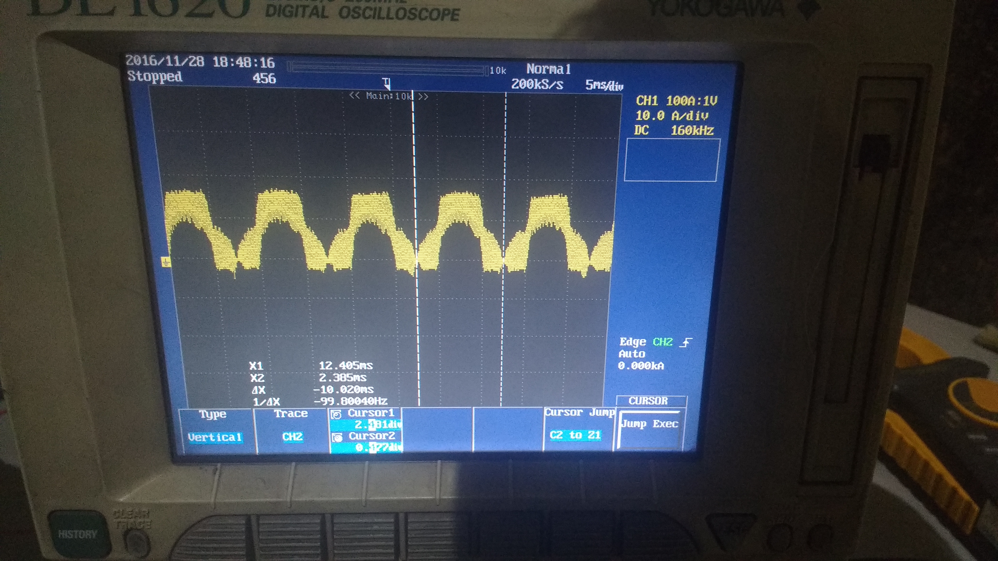
calculation sheet.xls   

  • Hello sagaRbhore,

    The calculator tool is telling you to use 4700uF output capacitance and you decided to use 2040uF.

    Then it warns you to increase the output capacitance to the recommended minimum so that OVP/UVD is not triggered.

    Is there some reason you are using such a low value of capacitance.

    It looks like the pfc is trying to control the input current but there is a lot of high frequency switching in the waveform.

    John Griffin

  • Dear John,
    Does capacitance can influence input current waveform at lower level of input current?
    High frequency switching is because of pfc IGBT switching only?
    Do I have to decrease switching frequency?

    Thanks & Regards
    Sagar Bhore
  • If you send me your schematic , design requirements and any more test data then I will be in a better position to help you.

    My email is johngriffin@ti.com

    High  frequency switching is normally filtered out by the input capacitance and EMI filter.

    Your current waveform has a very high frequency content and also a flat top which may mean that the current limit is being activated.

    Regards,

    John

  • My guess is: your inductor saturates or you have shoot thru in the diode.
  • Dear sir,

    I am sending you my circuit diagram and all data needed with waveform. PFC 8KW.docPFC CHOKE MIG 250 (CD)1.0.pdf

  • Hello Sagar,

    I checked the inductor and it will have a max flux density of 140mT so it will not saturate.

    Unfortunately the resolution in the schematic you attached is poor and I cannot read it.

    And the BOM is not complete.

    One other think for you to check :

    The current waveform may be indicating an overcurrent.

    The calculator tool recommends a 3mOhm current sense resistor.

    Item 130 in your BOM is a 250mV,50A current sense resistor.

    Are you using a 5mOhm resistor instead of a 3mOhm resistor ?

    Regards,

    John

  • John Griffin1 said:

    Hello Sagar,

    I checked the inductor and it will have a max flux density of 140mT so it will not saturate.

    Unfortunately the resolution in the schematic you attached is poor and I cannot read it.

    And the BOM is not complete.

    One other think for you to check :

    The current waveform may be indicating an overcurrent.

    The calculator tool recommends a 3mOhm current sense resistor.

    Item 130 in your BOM is a 250mV,50A current sense resistor.

    Are you using a 5mOhm resistor instead of a 3mOhm resistor ?

    Regards,

    John

    I think it will saturate. The datasheet is a bit basic. So I assume an AL= 413uH and the airgap of = 2.7mm(not 0.5mm, makes is worse)  at 50A B=0.683T.  Isat is app. at 27A.

    if the airgap is 5mm with an N of 22 =>  L=121uH and Istat=app. 43A still not enough.

    I think your design has a lot of issue. and don't think you got them fixed via this forum. maybe you have to rethink your design.