A related question is a question created from another question. When the related question is created, it will be automatically linked to the original question.
If you have a related question, please click the "Ask a related question" button in the top right corner. The newly created question will be automatically linked to this question.
Can you elaborate on what you are trying to test? Do you want to measure/verify the opto CTR?
What opto are you using, can you post the datasheet?
Usually the datasheet states the CTR at a particular forward current level If in the photodiode. You need to adjust the resistor in series with the diode to get the same level of current. On the photo-transistor side, you need to connect the emitter to ground, and add a pull-up resistor from the collector to a bias rail. By measuring the voltage drop across the pull-up resistor, you can measure the transistor collector current Ic, and thus the CTR = Ic / If.
You need to make sure that the pull-up resistor is not too large in value, so that the collector voltage does not drop to the Vce(sat) level. If this happens you will not measure the full CTR, but instead the saturated CTR.
If this answers your question, please click the "verify answer" button.
and also i have seen in one of the document, that CTR for an opto-coupler , is defined for a particular forward current, VCE, and for common collector configuration. is that true?
You need to replicate the same conditions as the datasheet.
In your results, the resistor connected to the collector is too large, so the collector voltage drops to saturation levels before the diode If reaches the same level quoted on the datasheets. You need to connect the collector pull-up to a higher bias voltage or decrease the pull-up resistor value, to achieve the same operating conditions quoted in the datasheet.
Referring to your first post on 3-Dec, for your test with If = 1 mA, Vce = 0.23 V & Ic = ~6 mA. This indicates that the opto has started to saturate, so you will not get the expected full collector current, and CTR will be lower than expected. If the bias voltage on the collector is increased, or the collector pull-up resistor is reduced to keep Vce higher than the saturation voltage, the CTR should be higher.
From the OLS249 datasheet, the spec at the top of page 3 says that with If = 1 mA, Vce = 5 V, the output collector current Ic should be in the range 2 to 12 mA. So the 6 mA you measure is already right in the middle of that range, despite that the output transistor has started to saturate. (Vce(sat) = 0.3 V).
Now to your second post above from 3-Dec. The opto CTR is never a fixed value parameter. It will vary from device to device, with temperature and operating conditions (If, Vce, etc), and it will even vary (decrease) over the life of the opto. Ungraded (i.e. unselected) optos can have CTR variation of 20:1 range or more.
Very often, manufactures will offer many graded options, i.e. where the devices are selected for different narrower CTR ranges. But even so, the CTR range will still vary of at least a 2:1 range.
For the OLS249 device, CTR can vary in the range of 200% to 1,200% under the specified conditions, hence the Ic range of 2-12 mA with If =1 mA.
For the earlier 4N24U device, the datasheet specifies only a minimum CTR of 100% at If = 10 mA - the max value or range of CTR variation is not actually specified. Your results actually do show CTR >100% even though If << 10 mA, except for the cases when If is very low.
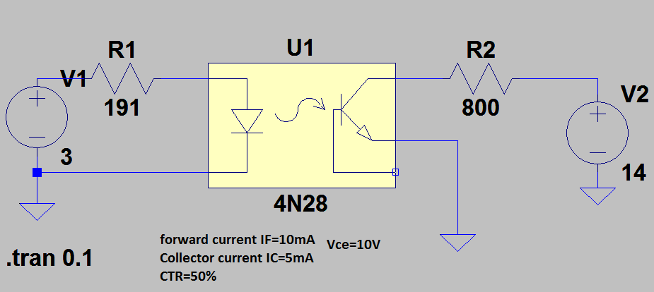
Finally, in your Spice simulation, the reason you get a 50% CTR is because I assume that is the value you have specified in the device CTR parameter field. It's displayed above under the opto device. For the 4N28, the datasheet specific CTR min of 10%, typ is 30%, and max is not specified.
As I noted above, opto CTR is never precise or exact, and varies. Your electrical design needs to be sure that it can cope with the minimum CTR, then it should be ok as along as the actual CTR is at or above this minimum level.
If this answers your question, please click the "verify answer" button.