This thread has been locked.

If you have a related question, please click the "Ask a related question" button in the top right corner. The newly created question will be automatically linked to this question.

TPS61088: TPS61088 freezing mystery

Part Number: TPS61088

Hi,

We boost 6V-9V input to 2A @ 12V using TPS61088.  The board normally works very well.  However, we have occasionally found the converter to freeze up and suddenly stop boosting.  This shuts down our system, so we notice it right away.  In the last week, this has happened 4 times.

The booster design is closely based on a Webbench design.  Attached is the schematic. 

Observations:

  • When the freezes happen, the converter had been running the system for a while (several hours).  Seems random, just not too often (maybe every 8 hours).
  • Nothing was happening special at the time … converter just powering our FPGA/CPU system on lab bench when it stopped.  No physical movement or change of load.
  • The freeze has happened on 3 different converter boards so far.  Also on two totally different power sources (once on battery, 3 times on lab bench supply … nominally 8V input).  And also on 2 different CPU boards as loads.
  • The boards typically run cool to the touch.  The board still feels cool when in frozen state (we touched within 2 seconds one time).  So I don’t think it is overheating.
  • When the freeze happened, we measured around the circuit and it looks like the converter should be boosting (see attached schematic with measured voltages we got one of the freeze times in red).  The converter has good input voltage and we confirmed that enable is set. 
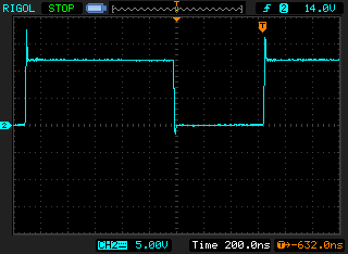
  • We saw no sign of oscillation on any of the nodes around the converter when frozen with oscilloscope.  Maybe the oscillator inside TPS61088 stopped???
  • If we take enable pin low then high again, the converter starts boosting again!!! 
  • None of the components appear to be damaged. 

I am guessing the internal oscillator of TPS61088 has stopped, and only a power cycle or cycling the enable pin gets it started again.  What could cause it to stop???  What else might be causing the freeze?  Any experience with similar?

As this doesn’t happen very often, I would really appreciate any ideas of what the cause could be.  Maybe we can setup a test to catch it and figure this out. 

Thank you for any suggestions.

  RyanTPS61088 frozen schematic.pdf


  • The boost converter has stopped two more times in recent days.  

    I think there are two questions here:

    1) Why is the boost converter intermittently stopping?

    2) Once stopped, why hasn't the boost converter restarted operation?   It looks to me that it has the proper conditions for operation when we probe after it stops. (Vin good, EN=H, normal load, ...)

    I think #1 is difficult without a theory to test.  Maybe if we can figure out #2, we can make progress.  What kind of state would the converter be in where it doesn't boost?  It seems to always start boosting again when the EN line is cycled.

    What happens internally when EN is taken high?   Is there a state machine to start up the boosting action?  What would happen if the booster was stopped, but EN is just held high.  Should it start up? 

  • From your description" Nothing was happening special at the time … converter just powering our FPGA/CPU system on lab bench when it stopped." So at the time TPS61088 stoped, there's a load  step , right?

  • Hi Helen,

    The load should be a pretty constant 1A @12V when running. There shouldn't have been any load change which causes it to shut down. I agree there would be a load step down afterwards due to the converter stopping. I imagine that after the TPS61088 stop, the output voltage drops from the normal 1A @ 12V to the unboosted input voltage of 0A@~8V. I didn't mention previously that the cpu board (load) has a shuts down circuit which trips when the voltage drops to <10V. So, when the output voltage drops below this, the load drops to near zero.

    Do you have an idea what might be happening? I surely must be doing something wrong. I'm sure these converters don't just stop intermittently like I'm describing.

    Thank you,
    Ryan
  • I check your schematic, some parameter need to be changed!
    1. compensation value: Rcomp=9.09k, Ccomp=6.8nF, Ccomp2=47p
    2. Add at least add one-more 22uF ceramic cap at the output side.
    3. For the Vcc cap C1, please use 2.2uF/16V/0603 cap. Or the effective capacitance will be too small.

    But most importantly, you need to check the output load status at the shutdwon to be sure it is caused by your system or the TPS61088. Because there are thoustands of customers and we never heard the similar problems. Your original parameter is not stable, revise the parameter  to make  the TPS61088 stable first to see whether it could be help.

  • Helen,

      Thank you.  I’ll make your suggested changes.  It will probably take a number of days before we see if it is working better.

      The compensation values we used are what Web Bench suggested.  (see attached).   Is the web bench design I got not stable, or did I not implement something correctly?   

      I notice that in normal operation, the converter is operating at the edge between continuous and discontinuous modes.  See below plots of SW pin under 1.3 and 1.5A load.  Our system is drawing ~1.4A.  So the converter may be changing modes sometimes.  Is that a problem?     

    8V in, 12V out @ 1.5 – SW pin (Continuous mode)

    8V in, 12V out @ 1.3A – SW pin  (Discontinuous mode)

    Finally, on the SW plots above, should we be concerned with the peak when the low side switch is turned off?  When I zoom into the peak, it reaches 17V and is back to 12V within about 10ns.  Does this  plot of the SW pin appear correct.

    Thank you for the guidance.  I will continue to investigate.   

    Ryan

    webench_design_392420_18_751798535.pdf

  • In the light load, it will work in DCM mode or even PFM mode, but in the heavery load, it will work in the CCM mode. If the system is unstable, it will shift between DCM mode and  CCM mode even at a fixed output currrent!
    The peak is a normal  phenomenon. it is caused by the parastic L and C in the circuit.

  • Sorry, I forget to say that the webench result is based on the 22uF effective output cap and a very wide bandwidth. But in your real system, you need to add more ceramic caps at the output side to make the effective capacitance under the 12V DC bias is >=22uF. Here I suggest you use 2-3pcs 22uF cap at the output side.