This thread has been locked.

If you have a related question, please click the "Ask a related question" button in the top right corner. The newly created question will be automatically linked to this question.

BQ25890: why BQ25890 charge current is always below 1A

Part Number: BQ25890
Other Parts Discussed in Thread: TEST2

I use R=220 for current limit on my board, so the IlimtA=355/220=1.6A.

And IlimtB is configured in the REG00. 

The current limit is the mimum of IlimtA and IlimitB.

The bq25890 automatically do voltage hankshake. In my test, I only read REG00, never write.

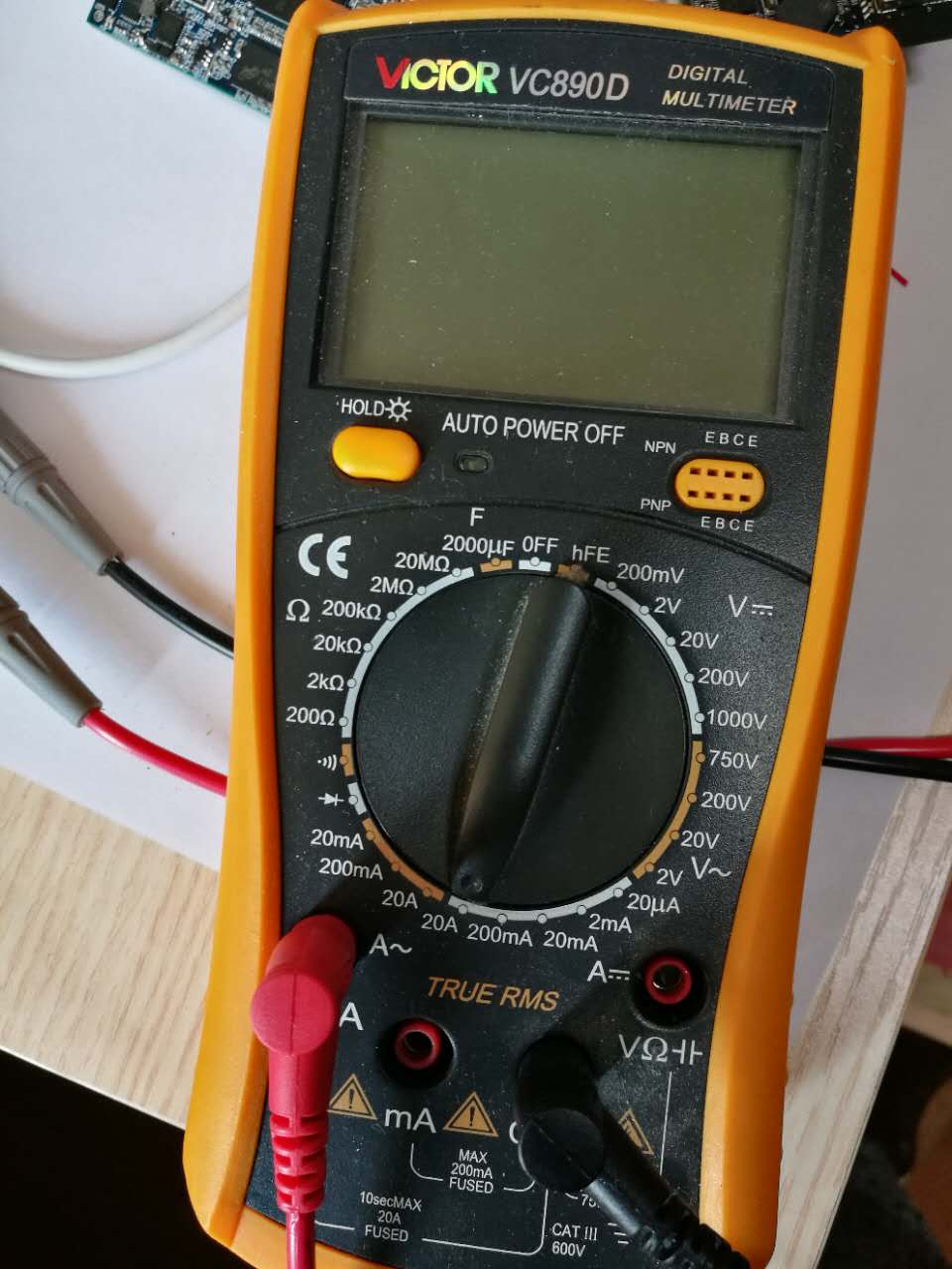
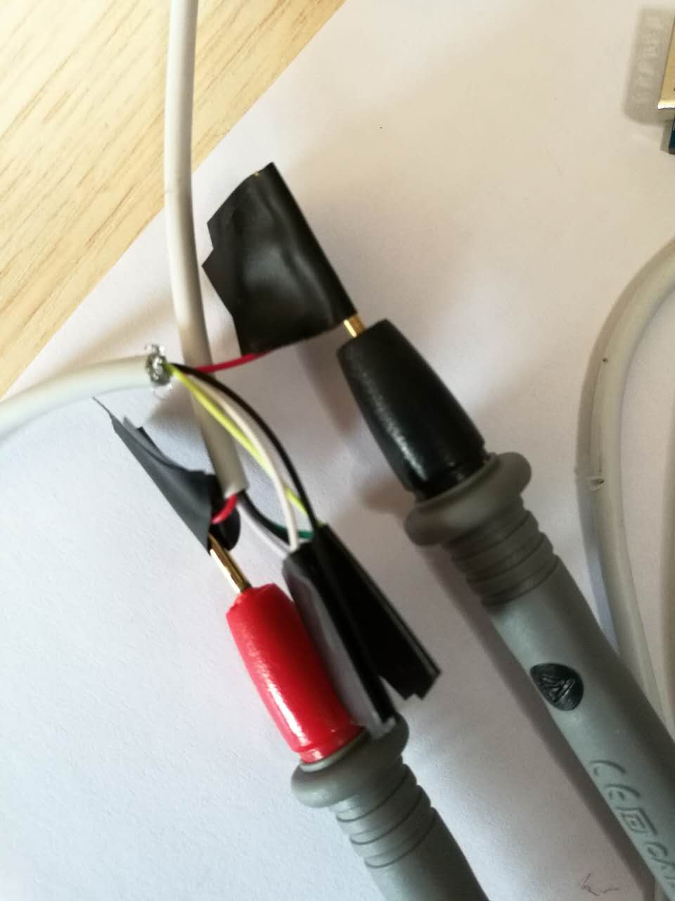
The current is measured with a multimeter, as shown below (only cut the VBUS wire and put it into the multimeter).

I didn't use any USB current monitor because they may support QC2.0\QC3.0\BC1.2, which will interfere the test.


I use a 2000mAH 1C battery. The battery is first depleted and charged with 500mA for 20 minutes before the test, to make sure it's not in the precharge or const voltage section.

No REG was written, so HVDCP_EN and MAXC_EN are both enabled by default.

The following is my test result:

Case

1

2

3

4

5

6

5V Power Supply

Ipad 2.1A charger

Iphone6 1A Charger

(Chinese)

Iphone6 1A Charger(Europe)

Desktop PowerSupply 3A,with D+D- shorted

Desktop PowerSupply 3A,with D+D- open

Laptop TypeC USB

Actual Current to the board

0.55A

0.41A

0.45A

795mA

472mA

0.46A

I think IlimtB should be

None Standard

2.1A

None Standard

1A

None Standard

1A

DCP

3.25A


SDP

500mA

SDP

500mA

Actual IlimitB read from REG00

REG00=104

2.1A

REG00=127

3.25A

REG00=72

500mA

REG00=127

3.25A

RE G00=72

500mA

RE G00=72

500mA

Q1. In CASE1, CASE2 and CASE4, IlimitB is 2.1A, 3.25A and 3.25A, why the current never get to 1.6A? (I have checked that, the R is 220 on the board for IlimtA=1.6A.)

Q2. Is MaxCharge compatible with QC2.0?

Q3. Is MaxCharge compatible with Apple Voltage Range?

Please help!

Thank you.

Frank

  • Frank,

    Regarding Q1, the resistor on ILIM pin only clamps the input current limit. For example, in case 4, where the D+/D- detection set IINLIM=3.25A, the resistor would clamp that value to 1.6A but in case 3, where IINLIM=500mA, the maximum input current is 500mA. The charger has two other features that can limit input current: VINDPM and ICO. VINDPM monitors the input voltage and if the voltage droops to the VINDPM threshold due, for instance, to a highly resistive connection from input power to the charger (for example, your taped connections and multimeter), the charger automatically reduces charge current to prevent more input voltage droop. The ICO loop will then reset the input current limit, to prevent future voltage droops, and report the new input current limit value in register 13. What is the voltage as measured as close to charger VBUS and GND pins as possible?

    Regarding Q2 and Q3, to achieve fast charging, high voltage (9V/12V) adapter with USB compatibility (5V) is required. TI refers such adapters as HVDCP (High Voltage Dedicated Charging Port) in general. Several companies have proprietary handshake to achieve this goal. However these handshakes are not industry standard, hence TI does not claim compatibility. QC2.0/3.0 is one that uses D+/D- handshake, while Mediatek PumpExpress is another one. These adapters all have an interface chip such as CHY100 (Power Integration) and iW62x (iWatt) included inside to handle the protocol. From market perspective, a lot of system vendors support this type of adapters with their own naming such as Adaptive Fast Charge (Samsung), Turbo Charge (Motorola), Boost Master (Asus). With so many different naming, there is no industry standard for us to claim compatibility. TI has tested and confirmed bq2589x can support HVDCP with these interface chips that includes Mediatek PumpExpress or QC2.0 support.
  • Hi Jeff,

             Thank you very much for your reply!

             Q1. Case 4. 

             The VBUS at the PIN1 of bq25890 is 4.54V, which has a big drop of about 0.46V at the wire and the PCB wire.

             I think you are right, the VINDPM and ICO limit the current.

             So I raise the Voltage at the soure to 5.5V, and get 5.05V at PIN1 of bq25890.

             I use a depleted battery.

             The current is 235mA at first, which may be at the Precharge Section.

             Ater several minutes, the current rise up to 780mA, and never raise up to 1A.

             I still don't know why the current can not raise up to 1A or evern 1.6A.

             Need for your help! Thank you.

    Frank

  • Frank,

    What is the voltage at the BAT pin?  If there is high resistance in the line from BAT to the your battery or battery simulator, then the IC will go into constant voltage (CV) mode too early and the charge current will start to taper.

  • Hi Jeff,

         Voltage at the BAT pin is 4.24V, and Voltage at the BATTERY is also 4.24V. The line is very short.

    Frank     

  • What is VBATREG register setting?
  • The registers were never written.

    I just read it out, It's the default value 0x5E. The same as the default value in the table.

  • Frank,

    Then you are in constant voltage mode and the current is already tapering down.
  • Hi Jeff,

    What sign is it that shows it's in constant voltage mode?
    And I have never see the current above 1A in the whole charging process, what's wrong?
    Frank
  • And I take another test:

    Time

    9:30

    9:32

    9:36

    9:45

    10:02


    Current(mA

    230

    792

    791

    791

    790


    VBAT

    3.04

    3.60

    3.82

    3.95

    4.04


    VCC_SYS

    3.75

    3.69

    3.89

    4.01

    4.1


    For example, at time 9:32, the Voltage at BATTERY is 3.6V and the Voltage at VCC_SYS is 3.69V, the current is 792mA. (Source 5.5V)

    And I read REG0B, the data is 0x76=b01110110, which means it's USB DCP(3.25A) and in Fast Charging mode.

    (By the way, according to the datasheet, the REG0B[1] bit is reserved and always read as '0', but I read '1'.)

    The VINDPM=600mV+3.9V=4.5V. The voltage at VBUS PIN is 5.05V when the source is 5.5V. So I think it's always above VINDPM.

    But, REG13 is read out as 79. Which means IDPM_STAT=1, IDPM_LIM=850mA.

    I think this is why the current is always < 800mA.

    But I still don't know why IDPM_LIM is automatically set as 850mA by the ICO algorithm.

  • Frank,

    ICO feature automatically lowers input current limit after VINDPM has been triggered.  So, in the past, the IC has attempted to charge at 1A (plus any system load current) but that caused a VINDPM event.  The ICO algorithm reduced input current limit to prevent another VINDPM event.  What is your system load?  Can you set the input voltage even higher or lower the resistance from power source to VBUS?

  • Hi Jeff,

    My system load is 150mA. And REG11 is 4.9V, which means the VBUS at the ADC is 4.9V. I think 4.9V is quite above VINDPM 4.5V.
    And I raise the VCC source step by step. Even when I set the VCC source as 6.0V, REG11 is 5.5V, the current is still only 740mA.

    And when VCC source is 5.5V, I take this test:

    ICO_EN=1, current=739mA.

    ICO_EN=0 (set via I2C), current=817mA.

    It seems that the limit is not only limited by ICO.

    I checked the Rlimit again, it's 220.

    So I changed Rlimit to 110, the current is still 820mA.


    I'm still confused about that.
    Is there anything that maybe wrong?

    Frank

  • Frank,

    Your maximum output current can be predicted with the following efficiency balance: eff = POUT/PIN = VSYS*(IBAT+ISYS)/(VIN*IIN) where you can get efficiency from the datasheet efficiency curves.
  • And when VCC source is 5.5V, I take this test:

    ICO_EN=1, current=739mA.

    ICO_EN=0 (set via I2C), current=817mA.

    It seems that the limit is not only limited by ICO.

    I checked the Rlimit again, it's 220.

    So I changed Rlimit to 110, the current is still 820mA.
  • Hi Jeff,

    Yes, the eff = POUT/PIN = VSYS*(IBAT+ISYS)/(VIN*IIN)
    The IBAT can be caculated with the equation. The IBAT is the unknown value.

    I think the IBAT has nothing to do with the BATTERY, it's only determined by the bq25890. right?
    The IIN is now 820mA when ICO_EN is disabled.

    Frank

  • Frank,

    What IBAT do you calculate?

    The charger sets IBAT to the value in the ICHRG register unless VINDPM, IINDPM (ICO), TREG, MAXDUTY reduces the battery charge current in order to provide more current to the system load.  Are you certain that your system load is only 150mA?  Once the BAT pin reaches the regulation voltage, the charge current starts tapering down.   

    The only other variable would be the inductor.  If not using a TI EVM, is your inductor current rating high enough (20% greater than your input current limit)?

  • Hi Jeff,

       1. The ICHRG is 2.048A, I never changed it.

       2. The system load is 150mA. VCC source provide power to the board without battery, the current is 150mA.

       3. Since the Ilimit=350/220=1.6A, and the ICHRG is 2.048A. The actual IBAT cannot get 2.048A.

            I mean the actual IBAT may be estimated by eff = POUT/PIN = VSYS*(IBAT+ISYS)/(VIN*IIN).

       4.  The inductor I use is SPM3020T-2R2M-LR, I think it's enough for the 1.6A input current.

  • With ICO_EN disabled, power supply 5.5V, I take the following test:

    The REG03 is read out '0x00', which means all the states are normal.

    And the state is read out as "Fast Charging"

    1) CHG_CONFIG disabled

        Isource=250mA                    (I use the CCS and run the read progm, so it's 250mA, not 150mA)

        (Isource means the current that the 5.5V power supply output)

    2)The following test are with CHG_CONFIG enabled:

    ICHG=128mA

    ICHG=256mA

    ICHG=512mA

    ICHG=1024mA

    Isource=350mA

    Isource=480mA

    Isource=660mA

    Isource=660mA

    It shows that, when ICHG=128mA\256mA, Isource increase the same amount as the ICHG.

    But 660mA is the limit in this test.

    I think it's the Charging Current that is limited.

    (660-250)*5.5V/4.1V=550mA      550mA is the actual current that is charged into the battery  (4.1V is the battery voltage at the moment)

    But there is no charging current limit circuits on the battery.

    There is only a DW01 chip, which is a protection chip which doesn't have any current limit function.

    Why the current cannot increase when ICHG=512mA or 1024mA?

  • Frank,

    Can you provide all of the status registers and the ADC for VBAT, IBAT, VBUS? 

    What is the TS pin voltage?  JEITA cool results in charge current being reduced.

  • Jeff,

          I only write ICO_EN=disable. Vsource=5.5V.

          Here is all the data of the registers:

    REG0 = 0x7F
    REG1 = 0x06
    REG2 = 0x4D
    REG3 = 0x1A
    REG4 = 0x20
    REG5 = 0x13
    REG6 = 0x5E
    REG7 = 0x9D
    REG8 = 0x03
    REG9 = 0x44
    REGA = 0x73
    REGB = 0x76
    REGC = 0x00 
    REGD = 0x17
    REGE = 0x5F
    REGF = 0x5F
    REG10 = 0x4E
    REG11 = 0x98
    REG12 = 0x08 
    REG13 = 0x3F
    REG14 = 0x1D

         REG0C=0x00, means no faults, TS=Normal.

         REG0B=0x76, means USB DCP, Fast Charging, Power Good.

         (The only problem is that The datasheet shows "bit1 of REG0B Reserved Reserved: Always reads 0", but what I read is always '1')\

    REG10 = 0x4E, means TS Voltage (TS) as percentage of REGN is 36.27%.
    REG11 = 0x98, means VBUS attatched, VBUS=5.0V.
    REG12 = 0x08, means IBAT=400mA.
    REG13 = 0x3F, means  Not in VINDPM, Not in IINDPM, IDPM_LIM=3.25A.
    REG14 = 0x1D, means bq25890.

    REG00 = 0x7F, means ILIM Pin enabled, IINLIM=3.25A.

    REG4 = 0x20 , means Fast Charge Current Limit=2.048A.

         The TS pin voltage I monitored with oscilloscope is 2.90V.

         I'm really confused why the charging current is only 400mA. Please help.

    Frank


  • Frank,

    The ADC is reporting the voltage at the BAT pin as 4.204V (REG0E), which means the charger is in constant voltage (CV) mode and the charge current is tapering off toward the termination current level.


  • Hi Jeff,

          Sorry, I made a mistake, the battery in the last test was full.

          And I take another test, with a battery that is not fully charged:

    ICO_EN=disable. Vsource=5.5V.

    This time, ISource=824mA

    The REGs that have changed are marked with red color:

    REG0 = 0x7F
    REG1 = 0x6                      VINDPM_OS=600mV
    REG2 = 0x4D
    REG3 = 0x1A
    REG4 = 0x20
    REG5 = 0x13
    REG6 = 0x5E
    REG7 = 0x9D
    REG8 = 0x3
    REG9 = 0x44
    REGA = 0x73
    REGB = 0x76
    REGC = 0x80                    Watchdog timer expiration
    REGD = 0x17                    VINDPM=4.9V
    REGE = 0x51                    VBAT=3.924V
    REGF = 0x52                    VSYS=3.944V
    REG10 = 0x45                  TS=32.085%
    REG11 = 0x97                  VBUS=4.9V
    REG12 = 0xC                    IBAT=600mA
    REG13 = 0xBF                  VINDPM, IDPM=3.25A
    REG14 = 0x1D

    This time the charging current is 600mA and it's in VINDPM mode.

    Q1. It seems that since the relative VINDPM threshold is used(VBUS=VINDPM=4.9V). It enters DPM mode, so the charging current is limited.

           But, VINDPM_OS=0.6V, why VINDPM=4.9V? How to caculate VINDPM from VINDPM_OS?

           I think there is no way that bq25890 can measure the Vsource(5.5V) (4.9+0.6=5.5V).

    Q2. But ICO_EN is disabled, why it enter into VINDPM mode? What is the difference of DPM and ICO?

           I think in the test, even ICO_EN is disabled, the chip still try to maxmimum the current with VINDPM limit.

    Test2:

    Then, I change VINDPM_OS=0.8V.

    This time, ISource=1103mA

    REG0 = 0x7F
    REG1 = 0x8                     VINDPM_OS=800mV
    REG2 = 0x4D
    REG3 = 0x1A
    REG4 = 0x20
    REG5 = 0x13
    REG6 = 0x5E
    REG7 = 0x9D
    REG8 = 0x3
    REG9 = 0x44
    REGA = 0x73
    REGB = 0x76
    REGC = 0x0
    REGD = 0x15               VINDPM=4.7V
    REGE = 0x54               VBAT=3.984
    REGF = 0x55               VSys=4.004
    REG10 = 0x46             
    REG11 = 0x95             VBUS=4.7V
    REG12 = 0x12             IBAT=900mA
    REG13 = 0xBF
    REG14 = 0x1D

    Yes, in Test2 VBUS=VINDPM.

    I think the problem is the Vsouce-VBUS drop is too big on my board. R=0.8V/1.103A=0.725

    Frank

  • Regarding Q1, relative VINDPM uses the VBUS when the charger is pulling no current. VBUS must be 5.5V when charger is unloaded if VINDPM_OS = 600mV and VINDPM is 4.9V. The ADC reads VBUS. You can set FORCE_VINDPM=1 to disabled relative VINDPM and sent VINDPM yourself.

    Regarding Q2, VINDPM always runs. When enabled, ICO lowers input current after a VINDPM event in order to prevent a future VINDPM event. I agree that your board's input line is highly resistive.
  • Jeff,

         Thank you so much for your help!

    Frank

  • Hi Jeff,

           How to judge whether bq25890 is in constant voltage(CV) mode or in constant current(CC) mode?

    Since, REG0B charge status only have:
    00 – Not Charging
    01 – Pre-charge ( < VBATLOWV)
    10 – Fast Charging
    11 – Charge Termination Done

    The "Fast Charging" doesn't tell CC or CV mode.

    Does it judge by VBAT==Vsys? Or does it judge by VBAT==Charge Voltage Limit?Or others?

    Frank

  • When V(BAT) = VBATREG, you are in constant voltage mode.
  • Do you mean by BATV==VREG?
    BATV is in REG0E
    VREG is in REG06
  • My board's input line is highly resistive (R=0.8V/1.103A=0.725).
    What do you suggest is a reasonable resistive?
    R<0.3 ? R<0.2?
  • VREG is BATREG=battery regulation voltage. BATV is the ADC measured value at the BAT pin.
  • R<=0.2ohm is not uncommon.
  • Hi Jeff,

    I take test with high voltage input, but face a new problem:
    e2e.ti.com/.../587986
    Can you give me some help?
    Thank you.

    Frank
  • Hi,

    Is there any source code where I can take for reference in writing the FW for this BQ25890 battery charger?

    This is a bit complex and sophisticated IC.

    Appreciate if someone can provide a reference code or flow how to properly make this IC operate, because I am worried damaging or over charging the battery.

    Thanks,

    jay