This thread has been locked.

If you have a related question, please click the "Ask a related question" button in the top right corner. The newly created question will be automatically linked to this question.

BQ76930: CHG/DSG abnormal

Part Number: BQ76930
Other Parts Discussed in Thread: MSP430G2402

Hi greeting

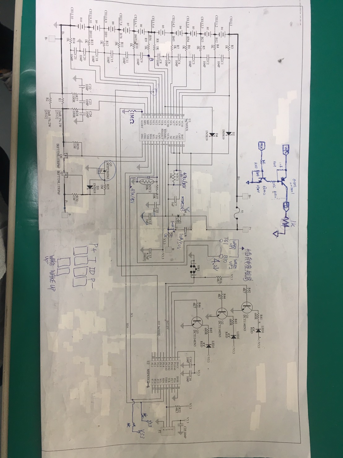
I'm helping my one of customer to debug the bq76930 + MSP430G2402 , applicaion 

application with 10 cell the first version schematic as attachment,

and their design was reference from the schematic at figure 8-2 bq76930 of SLUSBK2G this document.

The issue is about the voltage detect abnormal when adding the Cap (between VC10 - VC5x & VC5x - GND)

We'd like to know is there any set-up for Resistance or Cap need to be check again or F/W set-up could know the issue come from?

DESIGN PARAMETER as following:

Minimum system operating voltage: 25V

Cell minimum operating voltage: 2.5V

Series Cell Count: 10 cell

Charge Voltage: 40.6V

Maximum Charge Current: 3A

Peak Discharge Current: 2A

OV Protection Threshold: 4300mV

OV Protection Delay: 8 sec

UV Protection Threshold: 2500mV

UV Protection Delay: 16s

OCD Protection Threshold Max: 100mV

OCD Protection Delay Time: 1280ms

SCD Protection Threshold Max: 200mV

SCD Protection Delay Time: 400us

  • Hi Kay,

    What is the part actually doing that it shouldn't be doing?

    Thanks

    Miguel
  • Hi Miguel:

    Thanks, let me try to describe it more.

    The discharge function abnormal, about Cell minimum operating voltage: 2.5V; but actually protected at 3.1V around.
  • Hi Miguel:

    allow me to update again. We've further discuss about this issue and found:

    If each cell was not conduct to bq76930 at the same time (say about 10sec or longer), would that be an problem for bq76930 reading the voltage for each point? (from VC0 to VC10)

    I used a demo drawing to explain their way to conduct the battery to bq76930.

    hope this could understanding the question for now on. 

    BQ76930.pptx

  • Kay,
    the scheduler inside of the bq769x0 does a timeframe of 50ms window for the cell measurement when the cell balancing is OFF. A 12.5ms measurement window is generated by the scheduler, when the cell balancing is ON. A thorough understanding of the timing and the measurement is given in the application note SLUA775( Embedded Scheduler in cell battery monitor of the bq769x0)
  • Hi Vish:

    Thanks again!
    If we connect each battery with longer time interval (over than 2 seconds), would it cause the time-out issue for scheduler and which register could know the fault happened?
  • Hi,

    It seems there are entirely different questions being asked here.

    First question is about UVP tripping at 3.1V vs. 2.5V.

    Second question is regarding any affect to the part when you connect the cells the first time. When yo uconnect the cells to the 930 for the first time the bq76930 will not be turned on. It will need to be woken up with a pull up on the TS pin.
  • Q: If we connect each battery with longer time interval (over than 2 seconds), would it cause the time-out issue for scheduler and which register could know the fault happened?

    answer: if its from the cell 'connections' as you have highlighted in the pptx foil, the part is, tolerant to GND first and sequentially cell hookup from bottom to top. i.e as an example on the bq76930.cell #1, cell#2--cell#9,Cell#10 or GND First, then top down, cell#10, cell #9, cell#8...cell#2, cell#1. The time interval is NOT a criteria.