This thread has been locked.

If you have a related question, please click the "Ask a related question" button in the top right corner. The newly created question will be automatically linked to this question.

LM5160: fly-buck power supply

Part Number: LM5160

Hello

now I want to convert +5V to +6.7/-6.7 like the document in the below :)


look at page 3 and 16:

http://www.ti.com/lit/ug/tidud38/tidud38.pdf

look at page 17:

http://www.ti.com/lit/gpn/lm5160

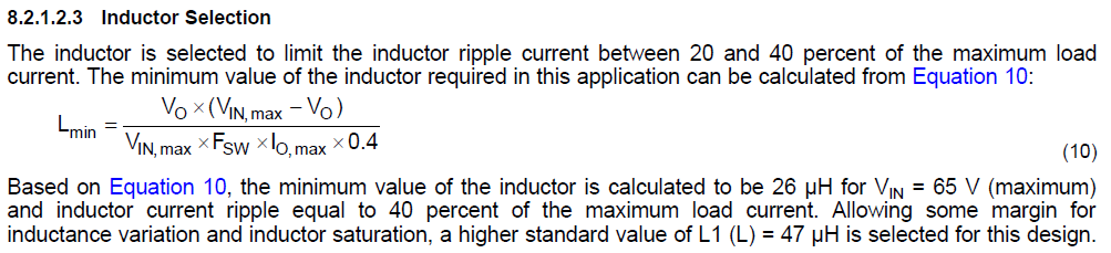
as per equation (7):


  • now the above frequency in "tidud38.pdf"  is negative!!! bcoz  Vin_min=5V and Vout=15V :)
  • on the other hand, how did they use TPA7A47 as 15V to 5V converter?! even with TI webench is not possible :)
  • How did they use LM5160 as a step-up converter?

Regards

  • Hi xyz xyz,

    You might need a 1:2 type of flyback transformer in order to achieve this as step up converter.
    Here are some design resources
    www.ti.com/.../design_resources.html

    One example
    www.ti.com/.../tidr999.pdf

    So you set the primary output voltage to be 3.5V then if you use the 1:2 flyback transformer then you have around 7V at secondary and minus 0.4V diode you get roughly around 6.6V on the secondary
    Some sample transformer
    www.ti.com/.../slpt047.pdf

    Thanks
    -Arief
  • it's not simply! I don't want to use opto-coupler :)

    the desired output current should be 1A :) but under 5W.

    https://e2e.ti.com/blogs_/b/powerhouse/archive/2014/07/24/when-is-fly-buck-the-right-choice-for-your-isolated-power-needs

    https://e2e.ti.com/blogs_/b/powerhouse/archive/2015/10/09/ask-webench-how-can-i-easily-create-a-fly-buck-converter-design

    what happened in "tidud38.pdf"? I want to have +/- 6.7V from +5V like their design.


    It's probably they used buck-boost technique.

    thanks

  • Hi xyzxyz,

    The schematic above shows a Fly-Buck-Booost configuration. Note that the primary-side output is -15V. The relevant duty cycle expression is that for buck-boost conversion.

    Regards,

    Tim

  • Yes, but now it violates the equation (8) in the LM5160's datasheet:

    even with TI's webench it's not possible to provide this voltage.

    I think I should consider |Vout| not Vout

  • I found a useful link:

    https://www.pddnet.com/article/2015/03/inverting-fly-buck-design-simplifies-bipolar-rail-generation

    how should I select Lmin (minimum value of inductor)?

    in the LM5160's datasheet there is a formula:

    but I think it's not true for this application bcoz I calculated above equation for "tidud38.pdf" and the value is 2.4mH not 100uH.

    on the other side there is a resistor at output of Vout2 and both grounds are connected to each other :

    thanks


  •  


    Dear
    I don't have enough time.
    after many months I'm finalizing my design.

    do you know how I should select the minimum value of inductor in the flybuck-boost converter?
    as per equation (10) above Lmin to be approximately 2.2mH (I used abs value)

    but I think it's not true bcoz in the document above, L is 100uH.
    I think Lmin=abs(vo1)/vi_max/Fsw/Iout/0.4=93.45uH (it's only a guess)
    where
    Vo1=-15.7
    vi_max=12V
    Fsw=200k
    Iout=0.175

    How about the switching frequency of the transformer?

    in another example the Fsw=140KHz but the designer selected a transformer with Fsw=200KH~400KHz. 

    or in the fig(28) in the LM5160's datasheet, the Fsw=300KHz but the designer selected a transformer with Fsw=150KHz.

    as per LM5160's datasheet:

    but in both examples the sat current of the transformers are below than 1A.


    Regards

  • Hello,

    As long as the peak current in the inductor is less than the minimum peak current limit of the LM5160 [2.125A], then you can use the inductance value in your desgin.  Also make sure that the transformer you use does not saturate at the max peak current limit level of 2.875A.  See the equations for flybuck boost attachedFlybuck Boost eqs.pptx

    Hope this helps? 

    kind regards,

    David.

  • Thank you
    1-I calculated the Lmin in other TI's flybuck-boost circuit using the equation I guessed above. the results are very close to each other. I think the
    L= abs(vo1)/vi_max/Fsw/Iout/0.4
    not
    e2e.ti.com/.../ind.PNG
    I think the equation above is true for a standard flybuck.

    actually when we read an article we pay attention to the total framework but in the later when we want to design a circuit we will understand the author didn't mention some key-role formulas in his article :)

    2-how about the switching frequency of the transformer? in both TI's circuits the Fsw of the both circuits is not in the range of switching frequency of the transformers. (bcoz I want to order the transformer from Digikey)
    3-why did they put a 3K resistor at the output of isolated output?
    4-in my design Vout=6.7 and Vin=5 so the duty cycle is 57%. is there any problem? bcoz I've heard the buck-boost converter depends on the duty cycle.

    Thanks

  • Hello,

    Please use the formula used in the ppt I sent in previous post.
    You will need to check the manufacturers recommended switching frequency and make sure your design is within the specified range. It will come down to the core material used.
    The 3.3k Resistor is a preload resistor. It is placed there to ensure that when the isolated rail is unloaded, the voltage on the isolated output does not peak charge the output cap way above the specified output. The preload helps hold down the voltage in the event that the isolated rail becomes unloaded.
    The Fly buck boost Duty cycle recommendations is 50%, from your specification you will be a bit higher than this. This should be ok as is is not too far away from the 50% recommendations.

    Hope this helps?

    David.
  • I really appreciate you for your attentions and recommendation.

    I used all the formulas but there is no formula to select the inductor value.
    I checked the formula that I guessed above. it works in all TI's circuits (only for flybuck-boost)
    as your words it's not easy to select a Transformer from Digikey.
    bcoz when I checked the TI's circuits there is no relation between the Fsw of the circuits and the frequency switching of the selected transformers.
    unfortunately most of the time there is no any spice models for inductors.


    Regards
  • Hello,

    I have gone through the math and you will not be able to get +/-6.7V out with 0.5A on each rail without the LM5160 hitting Current limit[from 5V in].
    I have calculated you will be able to deliver slightly less than this.

    With that said, try a coupled inductor with an L Primary of 22uH with a turns ratio of 1:1:1 for a low peak to peak ripple current in order to maximize the amount of current delivered at the outputs without hitting ilimit. The Isat on the coupled inductor needs to be greater than 2.875A.
     
    In Summary  suggest trying the following.

    Fsw = 500kHz.
    Lpri = 22uH
    Turns Ratio = 1:1:1
    Isat = 2.875A

    Hope this helps?